My hybrid Modular
Digital music electronics offers fantastic possibilities, especially for the control of synthesizers. To me, digital sounds often lack a kind of sensual factor, which is why I usually prefer analog modules for sound generation. The feel of playing with digital or analog sound generation is very different. Analog sound generators always have their own “individual characteristics” and are a mixture of strengths and weaknesses—much like humans—and the weaknesses can be extremely charming and quite decisive! They are responsible for “completing” the character. With digital sound generators, even with digital emulations of analog devices, there are no weaknesses, only “weak spots” — these are incompletenesses in the virtual image. Nevertheless, I naturally use a lot of digital sound generation — perhaps a little more in the background. I mostly program the digital elements myself in MAX (Cycling74). However, the analog sound generators are the main reason for the realization of my hybrid instrument.
The key feature is the digital control of the modules, which, especially in modular synthesizers, offers a number of possibilities that were previously “impossibilities” in such a system. This page therefore focuses on the conversion of control data generated by a computer into control voltages (CV). For example, envelopes, sequencers, random generators, LFOs, etc. can be generated on a computer and then controlled perfectly via software or complex MPE (MIDI) controllers and transferred to the analog modules. With the release of the Expert Sleepers modules (Audio-to-CV and CV-to-Audio) in 2012, my experiment of connecting MAX/MSP and the synthesizer finally got the green light. The Expert Sleepers modules were the “missing link.”
For the realization, the synthesizer must of course be expanded on the hardware side. Essential for this are a computer, an audio interface with digital outputs (AES, SPDIF, or ADAT), and the aforementioned Expert Sleepers modules, which are available exclusively in Eurorack format. I prefer the ES-40, which offers a choice of 40 CV or gate outputs with 5 CV expansion modules connected via a single SPDIF cable. In addition, a second SPDIF cable can be used to transfer two CV outputs from the synthesizer to the computer for recording control voltages from the modular synthesizer.
The desired modular synthesizer format (e.g., Eurorack, MOTM, MU, or Buchla) is irrelevant, as nearly all formats have 10V pp CV. The “pp” indicates that the range is 10V—it can therefore be either ±5V (i.e., -5V to 5V) or 0-10V. Different control voltages such as V/oct, Hz/V, or 1.2V/oct are also not a problem. However, the required trigger or pulse strengths can be an obstacle. Old ARP synthesizers, for example, require a 15V trigger, which cannot be generated with the newer Expert Sleepers gate expanders without their own power supply. The first generation(s) of the Expert Sleepers ESX-8GT, recognizable by the additional power ribbon cable, have two jumpers (for outputs 1-4 and 5-8) that can be switched to generate 11.54V. My ARP Little Brother has accepted this increased voltage, which does not reach 15V, as a trigger signal. Things get even more complicated with Buchla pulses (these are the Buchla triggers). I go into more detail about this on my Buchla page. However, as you can already tell from the photos, it's not impossible. This is my Buchla, which is mainly equipped with clones of the 200 Series (from the 1970s) and which I operate as a hybrid “electric music box.”
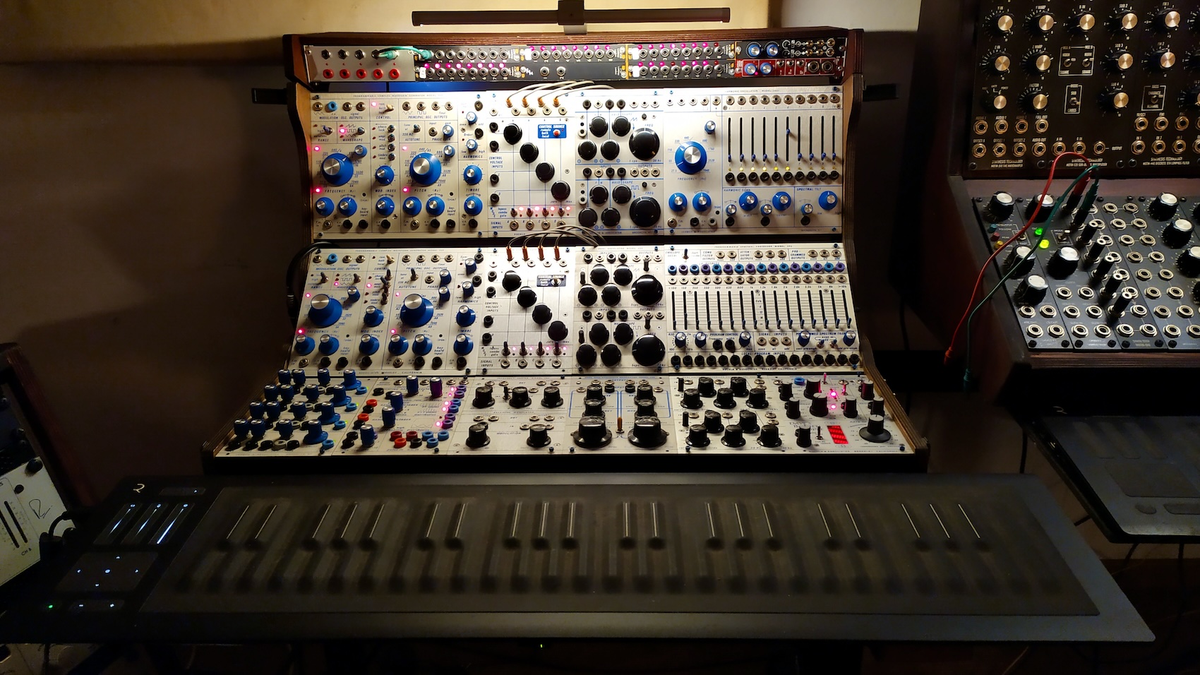
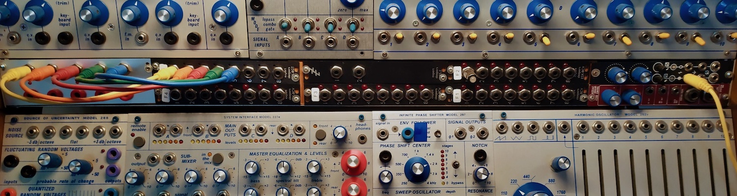
Don't be fooled by the small size (18U) of my newly scaled-down instrument. With only two exceptions (Source of Uncertainty Model 266 and Quad Voltage Processor 254v), only ”sounding” modules are included in the instrument. There are eleven VCOs (5 dual VCOs and one additive VCO (partial tone generator), ring modulator, frequency shifter, dual BP filter, comb filter, filter bank, spectral processor, eight low-pass gates, and a barberpole phase shifter. There are no envelope generators, sequencers, or other step or pulse generators (which are particularly large in the 200 Series), no matrix mixer, and no system interface. I do these things in MAX and control them via one or two iPads, where they can be accessed as tabs. Settings can also be accessed as presets. Together with the Rise keyboard, this corresponds to the size of a 200 Series Buchla of 50U or more!
With identical settings, it is impossible to tell whether, for example, the LPG is controlled by a Model 281 (function generator) or by MAX, or whether a step sequencer or MAX is running through the steps. However, MAX allows you to program much more complex envelopes than those from the Buchla modules. The envelopes can also be as long as required – if necessary, an envelope can take a week to run through. MAX step sequencers could have thousands of steps... And not only that: I no longer necessarily need to keep the “idiosyncratic” (i.e., not entirely accurate) tuning typical of Buchla. I have built in an automatic, individual calibration for each individual oscillator, so that I can play completely “in tune” or select specific micro-tunings. I am also not dependent on using one of the dual oscillators as an LFO. I can create any number of LFOs with all conceivable waveforms via MAX and use all existing hardware oscillators as “sounding oscillators.”
The following video should give you a first impression: at the top you can see the envelope curve used (in MAX), and to the right of it are five “modules,” each for one oscillator. The large white numbers indicate the MIDI channel from which the control data is received. I only play the RISE keyboard via MIDI channel 1, so I only control two VCOs, namely the first of each double oscillator, 158 and 258. At the bottom of the module are the names of the oscillators (in the first module “158A” for the first oscillator of the Model 158, in the second module “258r A” for the first oscillator of the 258r). In this configuration, five oscillators could be played with this envelope if all five were set to MIDI-channel 1. At the bottom is the individual calibration curve for the selected oscillator. The envelope shown in the video controls one channel of the “LoPass Gate Model 292” (instead of the “Quad Function Generator Model 281” module, which performs this function in the Buchla hardware setup).
Below is the outline for the MAX “module” for controlling an Oscillator from the Rise Keyboard (MPE):
The upper section shows the two menus that determine how the keyboard or keybed (RISE) is handled—the trigger behavior on the left and the note priority on the right.
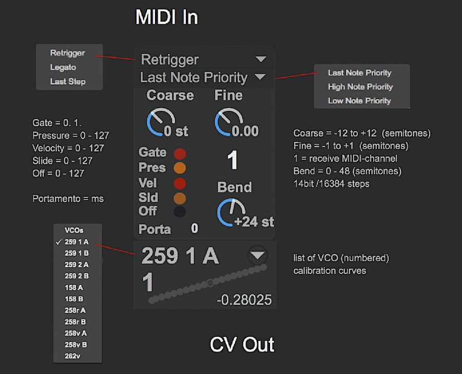 The middle section displays the transmitted controller parameters, which are significantly more extensive on the RISE, an “MPE” controller, than on a normal MIDI keyboard. I use them in an analog context as gate (on/off), pressure (aftertouch), velocity, slide (vertical “sliding” on the keys, or “keywaves” of the RISE), and OFF (release speed). Pressure, velocity, slide, and off all have a normal MIDI resolution of 0-127 (7 bits). For “important” parameters, I usually work with a finer 10-bit resolution (0-1023). The number behind portamento defines the milliseconds (2 seconds = 2000 ms). There is no limit to the maximum length. On the right side is Coarse—this is the transposition in semitones—and Fine Tuning (± 1 semitone). This is followed by the MIDI receive channel and the pitch bend range (max. 48 semitones). The pitch bend is designed in 14 bits, i.e. 16384 steps. There are two 7-bit strings as “MSB/LSB” (most significant bit/least significant bit). This means that for each of the 128 values (7 bits) of the first string, there are 128 steps (7 bits) of the second string, i.e. 128 x 128 = 16384 steps = 14 bits.
The name of the selected oscillator is displayed in the lower section, with the index number of the corresponding calibration curve, which is loaded automatically, displayed below it. Finally, the currently output value (-1. to 1.) is also displayed.
Envelopes
The next video shows three (of the many) envelopes that are looped and determine the sound shaping and pitch. The envelope at the top right is easiest to identify from minute 01:00 onwards, as it affects the pitch progression.
At this point, it should be apparent why I have removed the “Quad Function Generator Model 281” (or, in another format, the “Envelope Generator”) from the instrument, as the MAX envelopes can not only be duplicated at will, but are also significantly more complex. The video shows the AADSR envelope (2x attack!) with variable levels instead of the simple AD “function curve” of the Model 281. The 281 can also be used as a “kind of” ADSR when two channels are connected together – but then there are only two envelopes instead of four. Thus: no comparison!
Serge Envelopes
Serge synthesizers are known for their special envelope generators in which the curves are blendable. Here is an example with a "MAX Serge Envelope". Furthermore you can also hear a MAX Formant Filter. Just the two Buchla modules shown are active.
You might also notice that the combination of oscillator and LoPass Gate already provides the characteristic Buchla sound, i.e. the most minimalistic form of an "Electric Music Box". Even the formant filter programmed in MAX does not break the characteristic Buchla sound.
Movement Sequences
Progression curves can also be implemented very well. Shown here are 4 curves that run simultaneously from the beginning to the end (or vice versa) within a desired time period. Instead of the automated progression, a slider can also be used for positioning. The lower gray bar shows the current position.
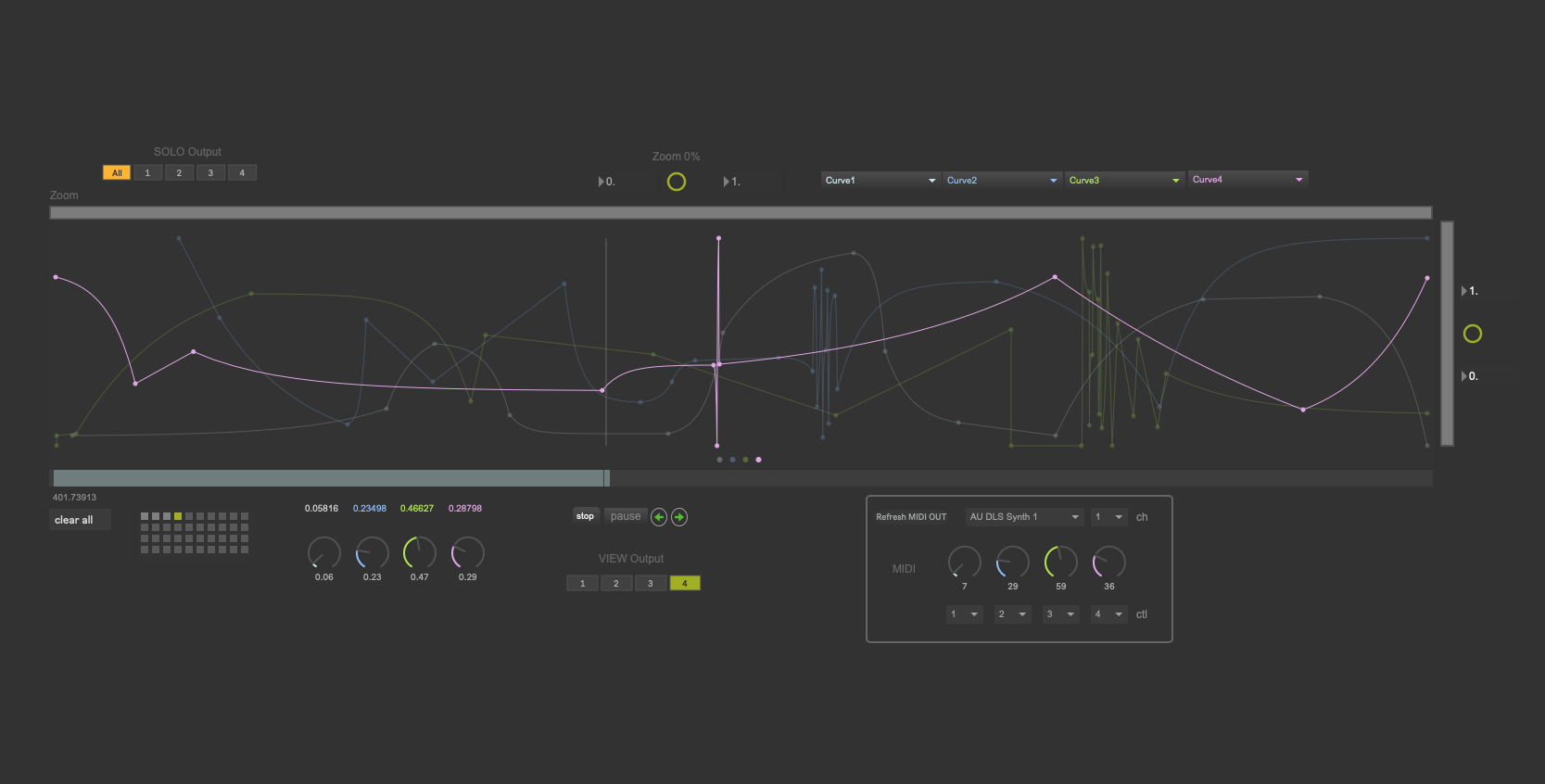
For the purpose of editing, the desired curve is brought into the foreground. Horizontal and vertical zooming is provided. At the top right there are 4 menus in which the names of the parameters are (may be) shown.
LFO
You can never have enough LFOs! This is a little "stress test" with a MAX LFO that can do anything you might expect from an LFO. Again only two Buchla modules can be heard: again the VCO Model 158 and the "Frequency Shifter Model 285" (as ring modulator).
Sequencing
Classical sequencers are not really my cup of tea, but the following can certainly be considered to be a form of sequencing. I organized "clocked" rhythmic groups, which are connected in tempo via a "Conductor Clock" ("Master") and run a number of "Performer [or Assistant] Clocks" ("Slave") in relation to each other, which access different note lengths. [Master & Slave are two such outdated terms, which I strongly refuse to accept.]
In doing so, I don't start a sequence, but trigger "performer clocks" using the keyboard. This makes it possible to play and does not reduce me to a starter/stopper. Here is another short example:
Control
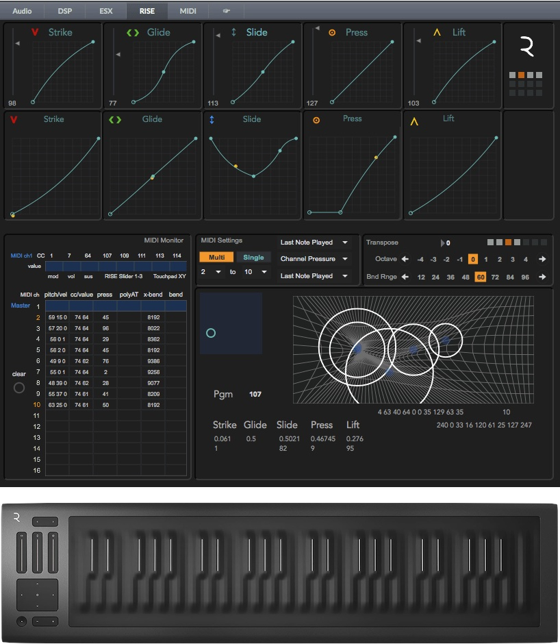 At this point I feel it would be useful to briefly mention the controller data. The key for the playability of the hybrid modular synth are the controllers. Shown here is the panel for the RISE keyboard, which I programmed myself (as a tab). This is where all the sections, separated from each other, can be set and all incoming and outgoing data can be viewed. The 5 curves are for setting the "5 Dimensions" of the Roli Rise and I have set myself 5 more curves for adjusting the curves to my playing manner (velocities etc.). Easily recognizable is the curve under "Press", which shifts the onset of the pressure curve a bit backwards, so only at more significant pressure begins to read out the upper curve. This way I don't have pressure (aftertouch) data all the time and with each remaining touch, but only when I really want it. And of course I can save different curves as presets in MAX. I am thrilled with the RISE Keyboard. To me it is ideal for playing synths, since I don't want to play the modular synth like a pianist.
In addition to the Roli Rise, I use one or two iPads and a few pedals. The iPads are very good controllers and are well suited for a 10bit controller resolution (0-1023). The computer doesn't need to be in view, but rather serves as a terminal - unobtrusive in the background. More about this can be found on this page under the menu Programming / Control.
The MIDI data generated here will be combined and "housed" in a stereo audio signal, which will be sent as SPDIF (digital) to the Expert Sleepers ES 40 module, and there again separated and routed to one of the 40 CV (or gate) outputs.
This shows the RISE well. In addition to the Buchla, you can also hear a comb filter which I programmed in MAX. Here, too, I find the integration of the digital sound to be just perfect.
Audio-Matrix
This is an audio matrix - to be heard only in stereo, in this example however 5 inputs are switched back and forth to 3 outputs. A matrix like this is a tricky business, because you have to make sure that the last output is switched off before the next one is switched on, otherwise amplifiers or speakers might be destroyed. At this speed it is breathtaking.
Calibration
Here's a slightly messed up video about the automatic calibration and my Calibration Module - for all 11 Buchla oscillators in my instrument.
iPad Controller
An old video - still with Eurorack - in which I had additionally made an iPad screenshot video. Seriously a fantastic controller! In the meantime I have learned programming much more complex setups. You will find more about this under the Programming menu Programming / Control
Also interesting: Replicate modules!
In the beginning, directly after the launch of the Expert Sleepers modules, I had recreated existing modules (programmed in MAX). Eventually, I had been using modular synthesizers for less than two years - a lot of things were not yet clear to me and it had been a pretty huge change after 30 years with ARP - nor did I have that much money for buying everything I was interested in. Two modules I never owned were the godfathers here: the "Rotating Clock Divider" from 4MS, which I however had extremely enhanced in MAX. You could not only perform simple divisions but also enter arbitrary values as divisors, e.g. in Fibonacci series. In addition, all parameters could be changed by controllers in real time and I had added an endless shift controller. The functions of the original module I had learned from the manual and watching several videos with it.
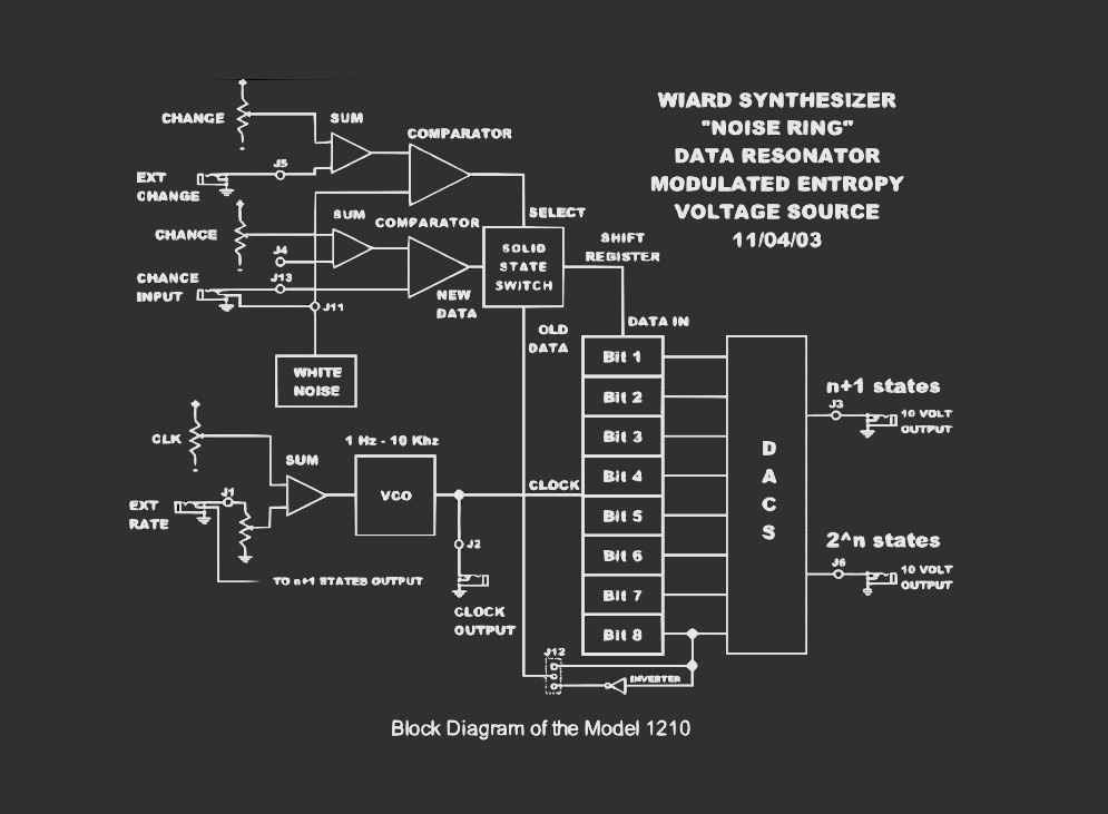
For the "Richter Noisering", a Random Generator built around a Shift-Register, I even found a block diagram - just what I needed to rebuild it using MAX! Like most shift registers (at least in the Eurorack) it is built around an 8 Bit chip (256 steps), white noise, two comparators, switches (gates) and an inverter for the "old Bit" - and voila! More than one owner of a Noisering module assured me that they could not find differences to the module.
It was an interesting experience discovering that the MAX modules were acting exactly like the hardware modules.
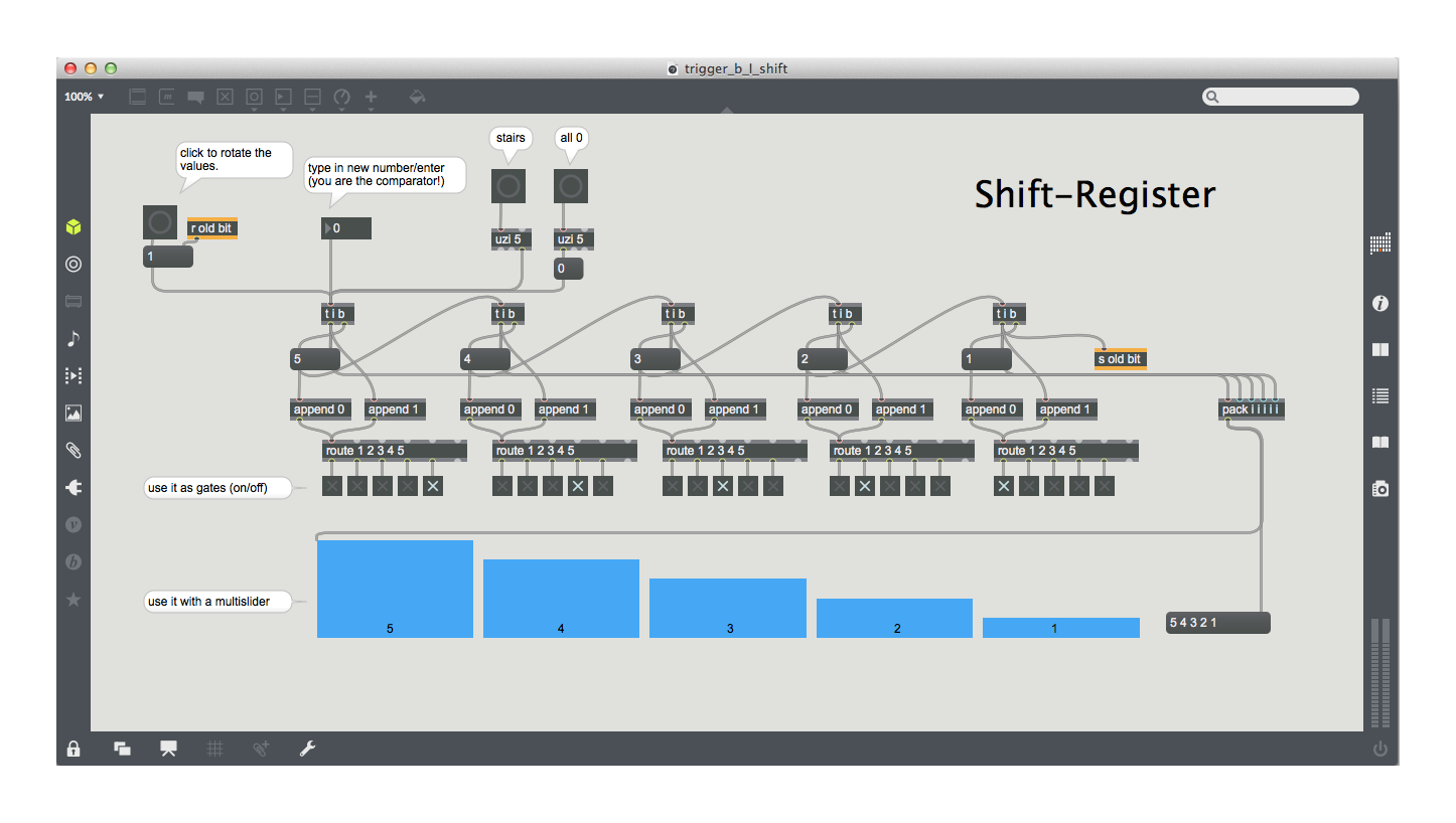
Ein Shift-A Shift Register passes the value of the first digit to the second digit, to the third, etc., as soon as the input value changes. This can be implemented in MAX, for example, as follows:
Example of a 5-digit shift register, which can be used as a gate selector or as a slider value.
Synthesizer
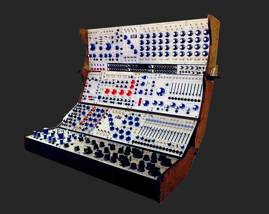 The Buchla 200 Series has been my "main" format since 2015 - the "Electric Music Box" of the 70s. Banana plug, unipolar, Tini-Jax, 1.2V/oct.... However, most of the modules in my instrument are not from the 70s, but fresh clones.
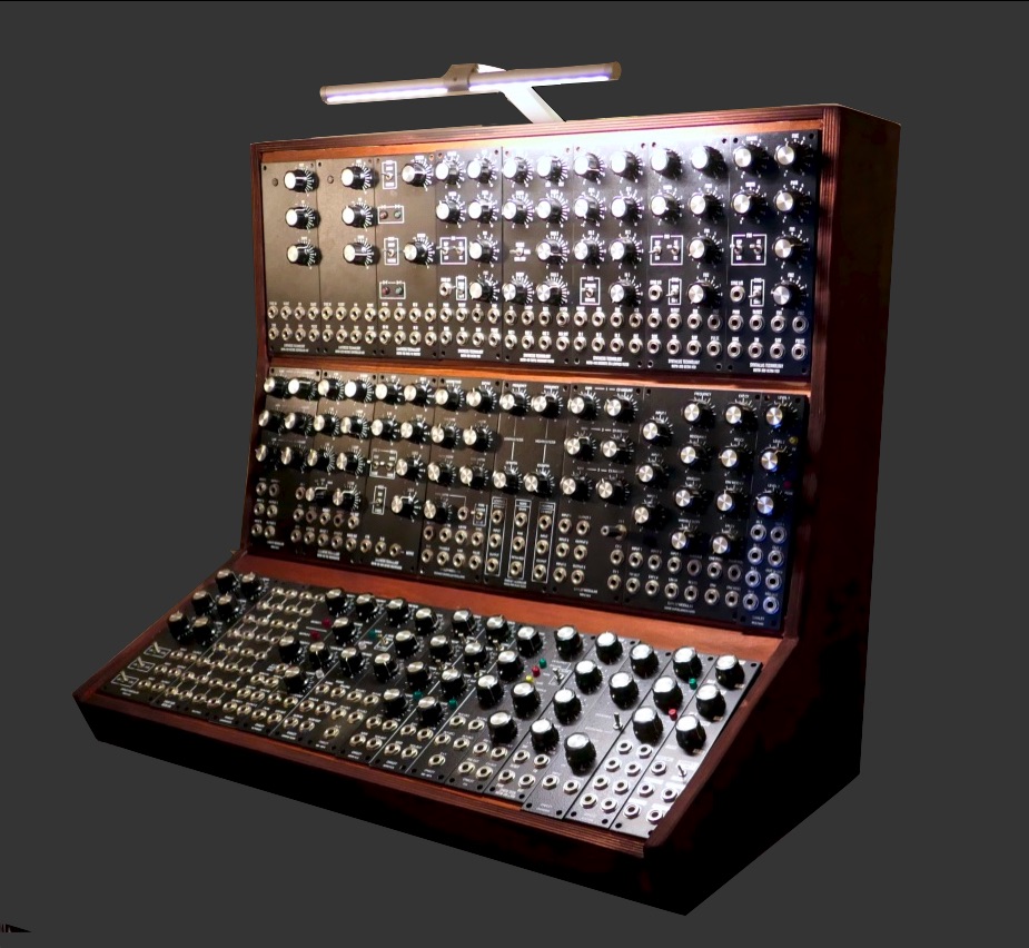 The high-quality key data of this 5U format are defined, the circuits of the modules originated from all directions. Heavy construction. Above all, it is worth mentioning the high quality of the components, which, in addition to excellent audio quality, also leads to a very good tactile feel.
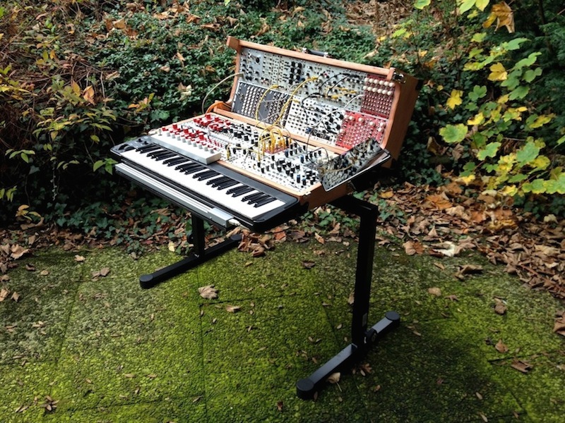 The most widespread format(3U). My last Eurorack instrument - 600TE, easy to fold in patched state, however I didn't feel comfortable with the small Eurorack format. Nevertheless, I still enjoy some blessed Eurorack modules to this day.
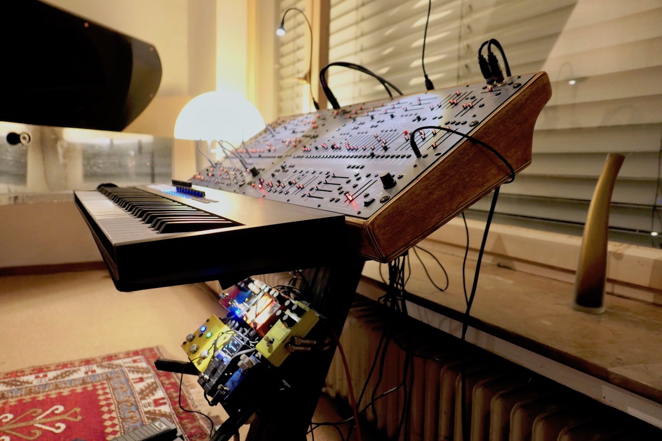 The Behringer reinterpretation of the ARP 2600 has succeeded magnificently! The B-2600 sounds a bit tidier, less exuberant than the historic ARP 2600 originals. From my point of view it's THE new "People's Synthesizer".
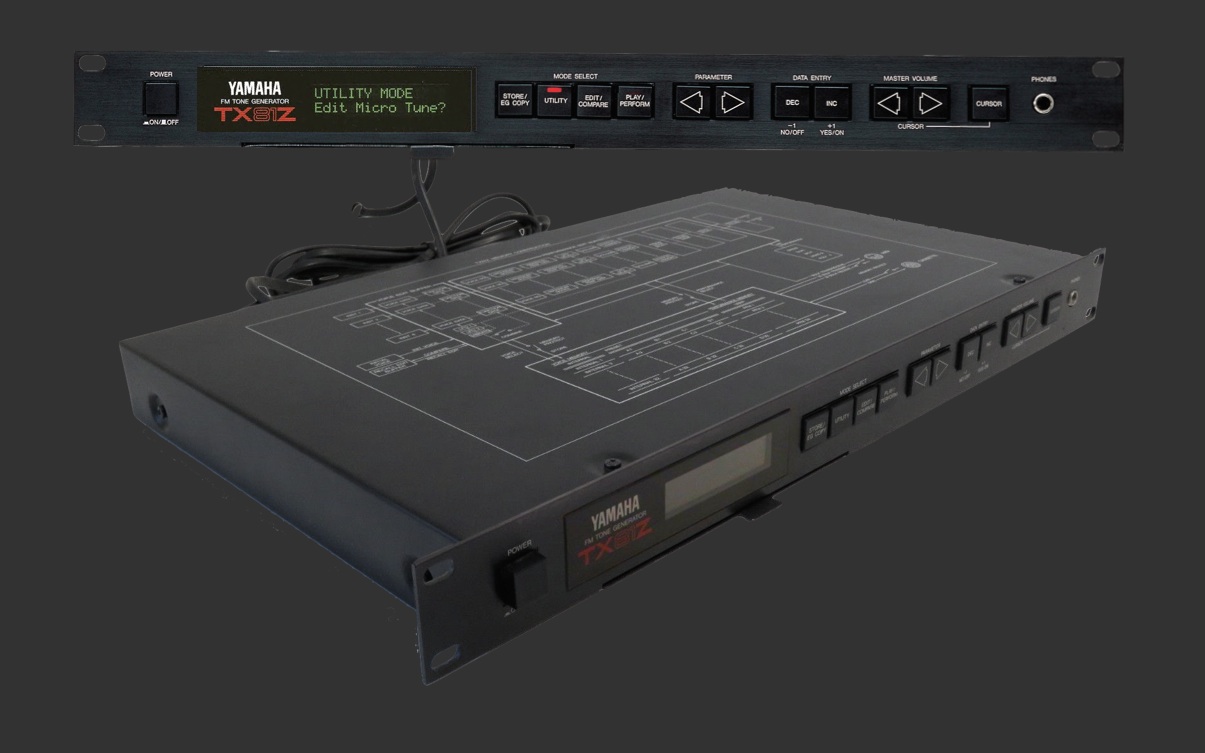 The TX81Z has 8 voices with 4 operators (= oscillators) each and was the first FM generator which provided the capability to also realize FM with non-sinusoidal waves. Because of its different tone generator it does sound better than the DX series.
 The second resurrection of a synthesizer that Behringer has given us, which I consider a very successful one and which is available for (almost) pocket money. Don't be fooled by the small size of this little gem.
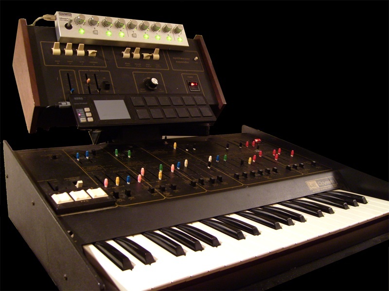 ARP instruments have been my choice since 1983. During the 80's and 90's Rhodes Chroma and ARP 2600, and since 2006, with the start of the " Hybrid Synth" project, it was this Odyssey featuring the Little Brother. An ARP overview from my perspective.
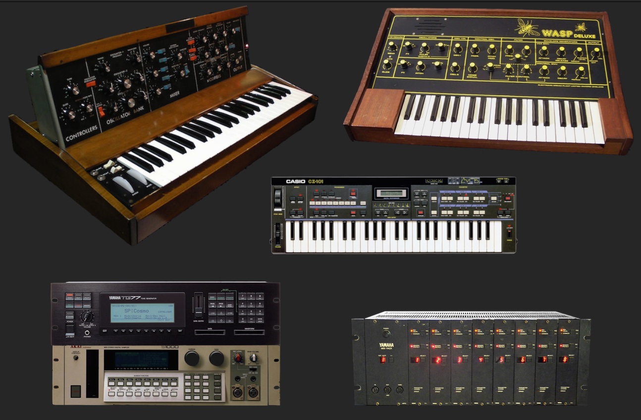 Some Classics that I had acquired in the modern era and the digital sound generators that I owned since the late 80's and with which I did a lot for about 5 years. They were especially interesting for me because of the computer and SysEx controllability.
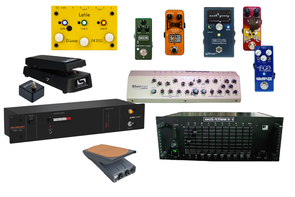 Synthesizers need FX devices!
Here is something about the peripherals: Filter Banks, EQ, Delays, Distortion, Phaser, Volume and Expression Pedals, Miniature MIDI Interface, Pedalboard and Power Supply.
