Buchla
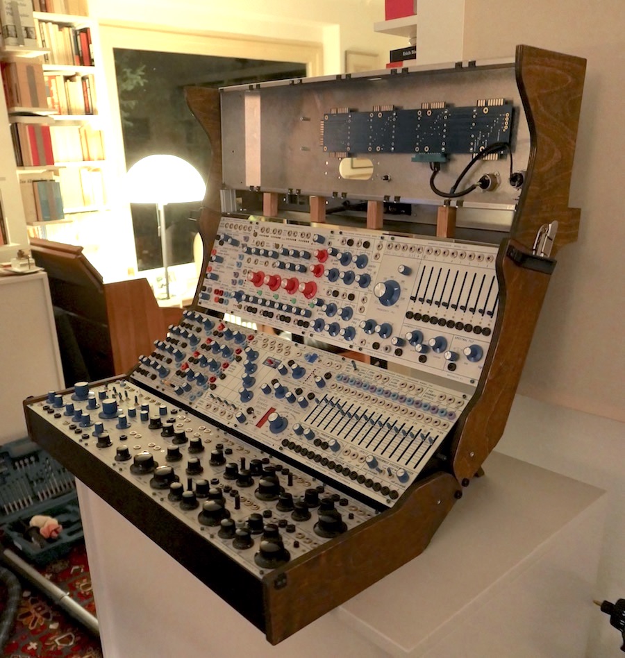
Electric Music Box
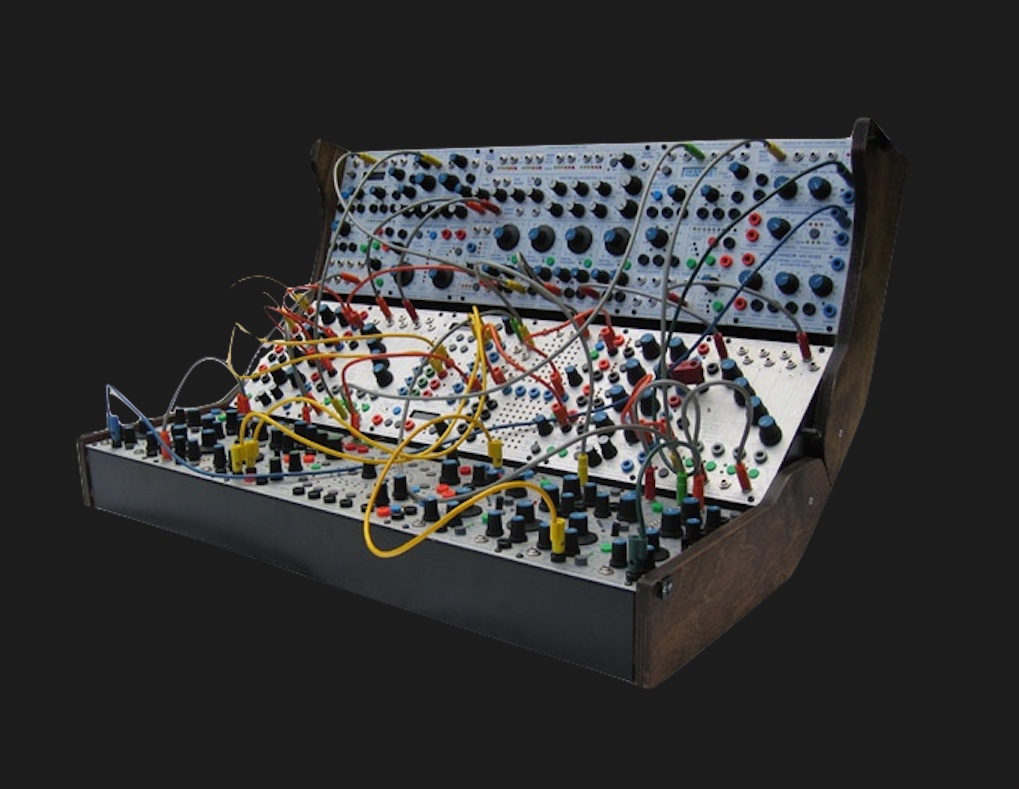
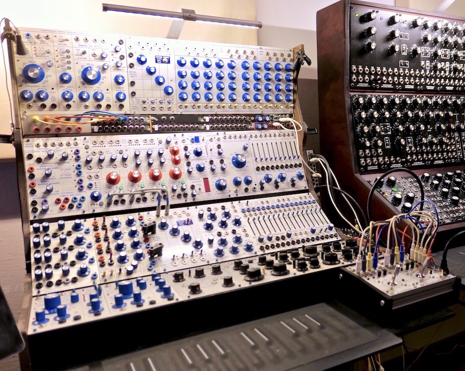
This is my instrument, mainly equipped with fresh clones of the 200 Series (1970-82). The small number of modules in the Buchla format seems almost limited in comparison, e.g. to the Eurorack - almost like a de-individualization. Nevertheless, the "Buchla 200 Series" has an unmistakable character, which is not just confined to the sound.
Clones do have the advantage of not being 45 years old and are considerably less expensive compared to the very rare originals. In some cases even defects or weaknesses have been corrected. How the differences to the originals are in detail, I can't judge, but I am extremely happy with these modules. Today, in 2023, having used these modules for 8 years, I'd go as far as admitting that, in my search for "my" electronic instrument, it was definitely my happiest decision in moving on to this format. But I have to emphasize that it's my "Hybrid Modular" from the point of view - i.e. the CVs are provided by the computer and I can calibrate (= tune exactly) each of my 11 oscillators individually at any time - and in just a few seconds.
Buchla Modular Series are roughly divided into the 100-Series (60s), 200-Series (70s) and 200-e-Series (since 2005). In the 80s there also were the 400- and 700-Series, which are however extremely rare.
One of the reasons that these modules are so interesting and different is that the mixing (audio) takes on a "different rank". Most functions are designed for adjustable weights. There are also very nice distortions to be created - sort of an extension of waveshaping, which is Buchla's other specialty. Very intuitive. I have had a lot of synthesizers - none has caught my heart like this one.
Don Buchla
Don Buchla (1937-2016) is one of the (for me) "big four" - that is Don Buchla, Robert Moog, Peter Zinovieff (EMS) and Alan R. Perlman (ARP) - also appeared on the scene roughly in that order (between about 1960 and 1970). I think all four of them got help from important friends or collaborators in the process, whose existence should not go unmentioned. Such great things arise in dialogue.
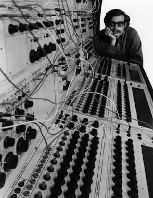
Don Buchla always was pretty much ahead with his developments - the modular 100 series, for example, was already introduced in 1963/64 (picture with the Maestro [photographer unknown]). For various reasons Buchla never had the "commercial breakthrough" - which certainly has to do with the fact that Moog and ARP found a wide range of customers mainly through the smaller stage synthesizers for rock and pop music, while Buchla rather worked with composers and universities who wanted completely different conditions/orientations. In addition, synthesizers were already expensive, but Buchla was very, very expensive. Since Don Buchla, the namesake and creator of this format, considered the term "synthesizer" misleading, he referred to his instruments as "Electric Music Box".
The instrument behaves amazingly similar (LPGs) to an acoustic instrument and is very pleasant and intuitive to control. The module panels layout was often designed first at Buchla, which is very unusual. The size of the modules (4U), the functional density, the physical distances between the controllers and the arrangement of the switches / controllers are the most successful for me (compared to other formats). The intuitive access is additionally supported by the striking arrangement and the easily distinguishable appearance of the modules. Because of the different layout (Waveshaping/LPG) and the California origin, the term “Westcoast” established for these instruments.
Electric Music Box
A sonic impression of my Buchla Electric Music Box (200 Series). More sound samples can be found at "My hybrid Modular".
Buchla 200-e Series
The current 200-e Series: a very pretty system - though not cheap. The pictured instrument (18U) is priced between € 22,000 and well over € 30,000, depending on the configuration. A highly desirable instrument - actually without direct competition in terms of possibilities. I only have little experience with this series and therefore can only describe my single "experience" with it - it wasn't very positive, but my summary still includes "neutral" information about the 200-e Series.
In 2012, I had intended to start with Buchla - yet with the e-series. After looking deeper into a Skylab (10U), however, no joy would arise. The workmanship seemed suspect to me, many controls felt very wobbly and two of the 10 modules didn't operate. I disliked the sound of the 261e (compared to the oscillators of the earlier 100 and 200 series) - and unfortunately it was the only built-in VCO.
The (quite interesting and unique) preset management is rather standing in my way, because I do just that with MAX (cycling74). It would be a complete sub-level to be controlled, which would bring more complications than benefits to me, besides I prefer not to have modules with any firmware. The e-series also is very much designed for the trigger and sequencer pulse world, which is another thing I have very little to do within this framework. Therefore there are much more pulse I/O's in the e-series than in the predecessors, because with these you can also call up sub-presets in modules. For example, in the Triple Morphing Filter 291e there are 3 "Nodes" with 8 "Stage Numbers" each. I.e. an integrated step sequencer with 8 steps and 3 busses is used for storing the 3 filter values etc.. With Pulses it is "stepped through" and with CV interpolated (I think it is interpolation and not morphing).
The e-series has grown in performance and compressed in size at the same time compared to the 200 series. The Dual BPF 291, for example, has become the Triple Morphing Filter 291e. The 227e system interface has shrunk while still offering additional capabilities (the only e-Series module in my system). For me, the Matrix is a highlight of the 200-e Series, but (fortunately) one that I don't need either.
Hence: a great concept - but not for me. Perhaps I will add more e-Series modules at some point - although I prefer to build my basic system on the basis of the 200 Series clones, which I clearly prefer in terms of sonic qualities.
Note: In 2012 the company Buchla was owned by an Italian consortium, which almost destroyed the company. In the meantime "Buchla" is in better hands again - in the USA - and staffed very well.
Buchla
Buchla Details
Since Don Buchla didn't necessarily see keyboards as ideal controllers, he provided alternative control modules right from the start - for CV there were various touch-plate attenuator variants and very idiosyncratic sequencers, for audio it was rather more complex matrix mixers.
Buchla uses 0-10V control voltage, but is unipolar (positive values only). Therefore audio (bipolar) and CV are handled separately and on CV connections 4 mm banana plugs (lamella plugs) are being used.
The audio plug format is the rare Tini-Jax .141 from Switchcraft. Tini-Jax is minimally larger than 3.5mm mini jack and looks confusingly similar. Tini-Jax plugs come in metal and plastic versions.
Mini-jack plugs don't stick as tightly, but they also work and can therefore be used in the Buchla without hesitation - but not vice versa: Tini-Jax plugs are a tad too large for the Eurorack sockets!
Buchla uses line level of 0dB/600 ohms for audio (instead of +12dB/150 ohms, as used in Eurorack).
Buchla uses 1.2V/oct (instead of V/oct or Hz/V).
Buchla Electric Music Boxes operate internally with 15V - even if they are supplied with 12V power supplies! The original 100-Series and the very early 200 modules were still supplied with 15V (and partly even higher).
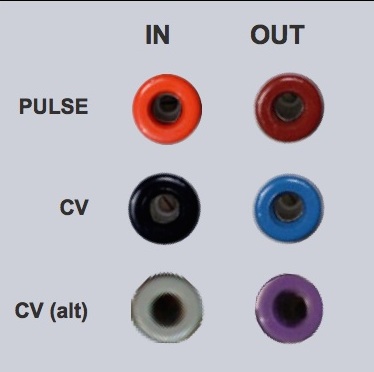
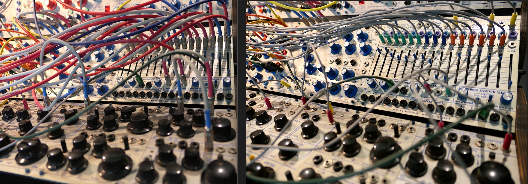
The banana jacks are subject to a color code. Orange for pulse inputs and red for pulse outputs, black and gray for CV inputs, blue and violet for CV outputs. The alternatives (gray/IN and violet/OUT) are only used if in- or outputs are present in larger numbers on the module.
On the 200e series, the knobs are also color-coded: the positions of the blue knobs are stored in the preset, those of the white ones are not.
My Buchla
Since I prefer the (historical) "200 Series" and the Programming Environment "Max/MSP" is of central importance for me, I skip a large area of modules. Especially in the e-series this area plays a central role (e.g. sequencer, touch panel, matrix router and preset management).
The modules are undoubtedly interesting - but not for me. I want to do these things with Max. So even if these modules are attractive for as many Buchla friends as possible, or are the reason for choosing Buchla - I have no ambitions whatsoever to acquire them and will report only on the details of my instrument in the following. I will discuss the computer connection (Audio to CV) here: My hybrid modular synthesizer.
I have placed the Eurorack modules (mainly Expert Sleepers [Audio to CV]) underneath the upper Buchla-Boat. Power and ES-40 (SPDIF I/O) I placed on the rear (see below), because I don't need them for playing. That's a "valuable" 10HP, which also allows me to keep the low 8HP in height for the Eurorack "strip" in front. Besides the Expert Sleepers modules, there are pedal interface (sustain and expression), dual VCA and Gate-to-Pulse converter built in. Of course the Eurorack modules got their own power supply. In addition, there is a mini-case (front) with two Vector mixers (joysticks), which are connected to the instrument via dual Ethernet audio multicore wires.
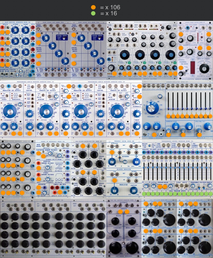
The Modules in my Instrument
Programmable Complex Waveform Generator Model 259
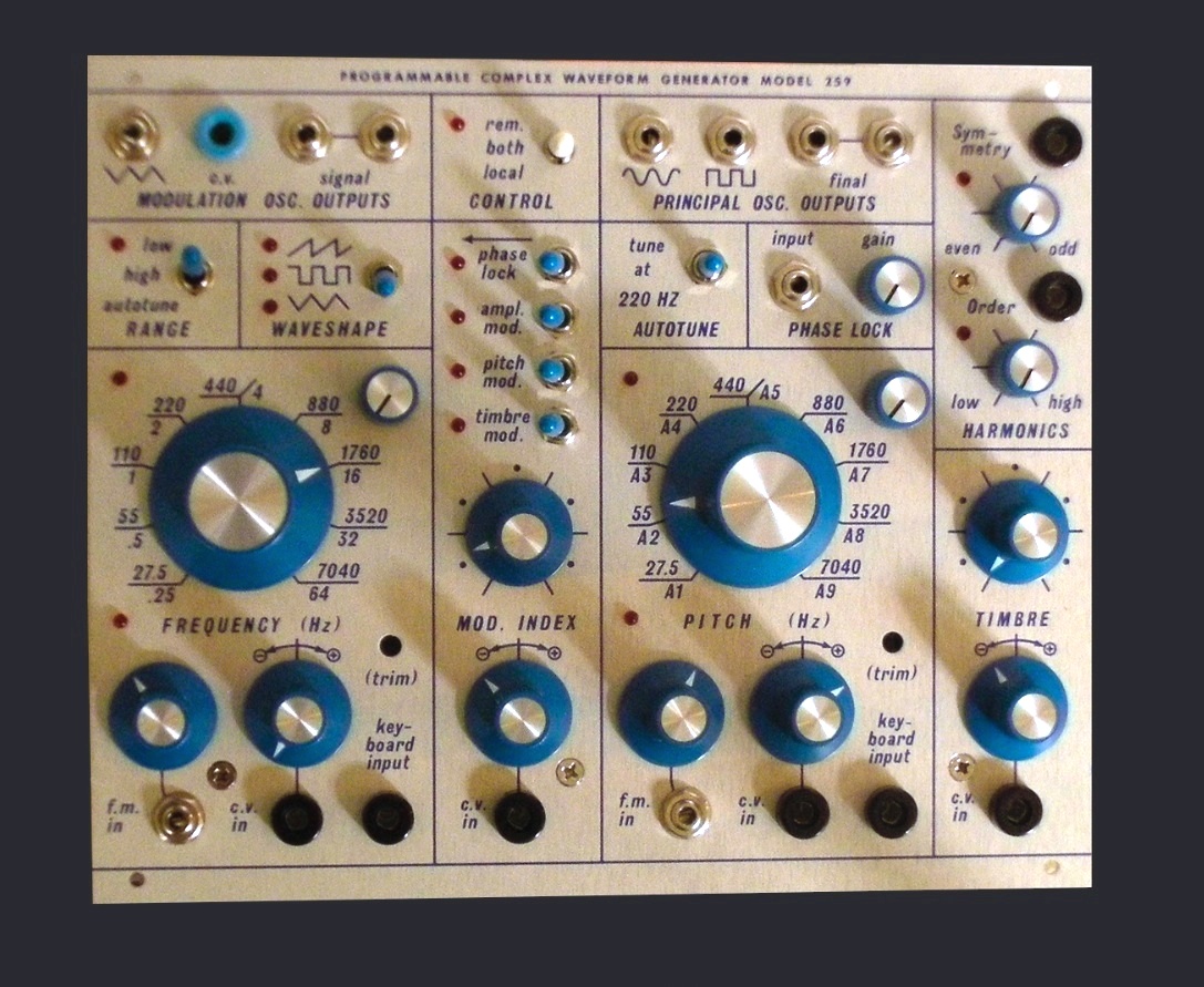 The "Programmable Complex Waveform Generator Model 259" (left) is a Dual Oscillator with Timbre Modulation. In particular, the 259 makes clear why Buchla needs fewer modules. Of course, the circuits are also possible in other formats - but they require 3-8 modules for the same tasks (ie 2x VCOs, VCAs, Attenuators, Waveshaper etc.). The division of Shaping into Timbre and Harmonics with Order and Symmetry came only with the Model 259 and makes this Waveform Generator a truly royal module. The Banana CV-Out of the left Oscillator is another advantage of the 259.
Buchla VCO's are designed for Frequency Modulation and Waveshapping, and Buchla is arranged "differently" - also modular, but the groupings of the functions are combined in selected combinations in such a way that a basic instrumental characteristic arises.
Dual Oscillator Model 258 und Model 258v
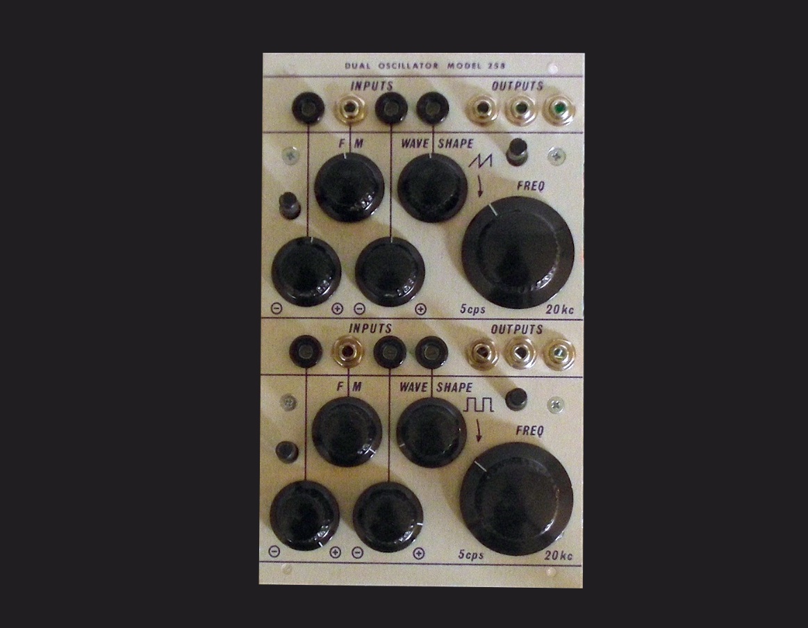 The "Dual Oscillator 258" (right) is perhaps "the" classic Buchla VCO. The upper Oscillator is Sine to Sawtooth, the lower Sine to Rectangle.
There are at least three Clone versions of the Model 258, which is the Model 258r, the Model 258r with historic components and the Model 258v, by Mark Verbos. I own the two last-mentioned variations, which, in all diversity, both have their merits. The Model 258v has CV inputs instead of the "Fine Tuning" pots. My favorite is the model with the historic components, because it is somewhat "eggier" ;-)
What fascinates me about this Double Oscillator is how immensely "straight forward" it is. It raises no questions, has clear playing fields (top sawtooth / bottom rectangle), allows cross modulation and sounds just like the "VCO for the island".
Harmonic Oscillator Model 262v
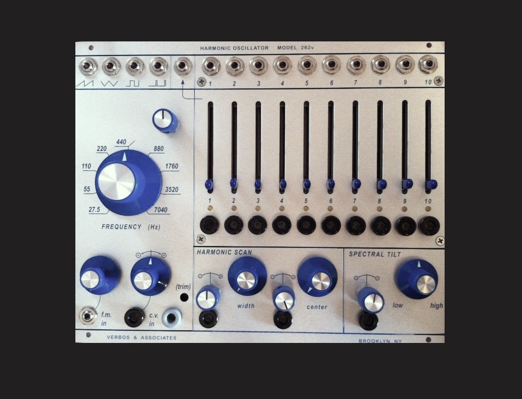 The "Harmonic Oscillator Model 262v" (left) is an additional oscillator with 10 Partial Tones. Apart from the single Outs of the Partial Tones, it (of course) also has a mix output for all Partial Tones. At least Saw, Tri, Square and Pulse have dedicated outputs. The Volume of the Partials can be controlled with the sliders or via CV Inputs (black).
Since Mark Verbos now has a well-known Eurorack series, in which there is also a Harmonic Oscillator, many will ask where the differences lie. Obvious are the two additional sliders on the 262v. They are not just two sliders: they are two important overtones that extend the harmonic spectrum considerably, because they go beyond the octave (and thus over the "triad characteristic).
The 262v is better controllable (the Eurorack module is somewhat obscure) and the Euro VCO is based on the Model 258 Oscillator, while the 262v is based on the Model 259 Oscillator. Well - and Euro is 12V.
Dual Sine-Sawtooth Generator Model 158
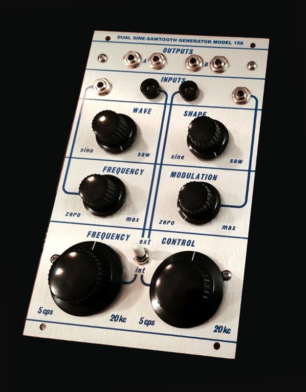 This Double VCO is the replica of the 100 Series (1963-70) Oscillator, the "Dual Sine-Sawtooth Generator 158" - the predecessor of the 258. The 100 Series always appealed to me because of its crudity. The replica does not attain this entirely, but has other advantages, e.g. a much better tuning stability. Also, the 100 Series is not as completely CV-controlled as the 200 Series and therefore needs to be operated more manually.
The Model 158 is just as straightforward as its successor, but has only the Sine and Sawtooth waveforms, while the 258 provides one Saw to Sine and one Sine to Rectangle. The 158 Oscillator is just wonderful and I do not want to do without it. 158 and 258 have the "famous" Buchla trembling. I like that. Sounds like the big time of electronic music.
Quad LoPass Gate Model 292c
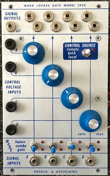 Filters do not have the central position, as with VCO/VCF/VCA/ADSR "Eastcoast" systems (Moog, ARP). There are still some. The reason for the less central importance of the Filters is mainly due to two things: firstly, the Waveshaping is to be regarded as an alternative to filtering and Buchla works with Lowpass Gates (VCFA) instead of VCA - this creates "more natural" ins and outs - overtones change with the volume (or opening of the LPG). Therefore, I would call the LowPassGate 292 as a "typical" Buchla module - it also visually stands out clearly by the diagonally arranged buttons.
LowPassGates are, technically speaking, VCFA - whereby Filters and Amplifiers are controlled coupled. The 292 module offers a VCA and a Combo Mode as well. In the Lopass-Modes, the 292 is one of the most sonorous modules and is highly responsible for the "Buchla sound". At the 292, it is also time to mention the weaknesses, since some applications may require a workaround: the 292 does not completely close and should therefore be lengthened by a Gate or another VCA. Another "weakness" that is perceived as an award, is the Vactrol control: it works through optical resistors and is quite slow.
Dual Voltage Controlled Filter Model 291
 The Model 291 is a double bandpass filter and not everyone's cup of tea. It is sonically very distinctive, therefore easy to identify and sounds "very old-fashioned". These kind of pure/exclusive bandpass filters were the first filters used in electronic music (e.g. the Maihak W49 radio play distortion from the 50's).
Pure bandpass filters are rather rare today and bandpass is usually only implemented as part of a "variable state filter". If high-pass and low-pass are combined, they also result in a bandpass. The Vactrol control (light signal source and optical resistor) of the Model 291 additionally forms the very own character. Light pipes are, contrary to the assumption, rather slower. Vactrol controls have a noticeable inertia.
I like this filter - what a great destroyer!
Frequency Shifter Balanced Modulator Model 285
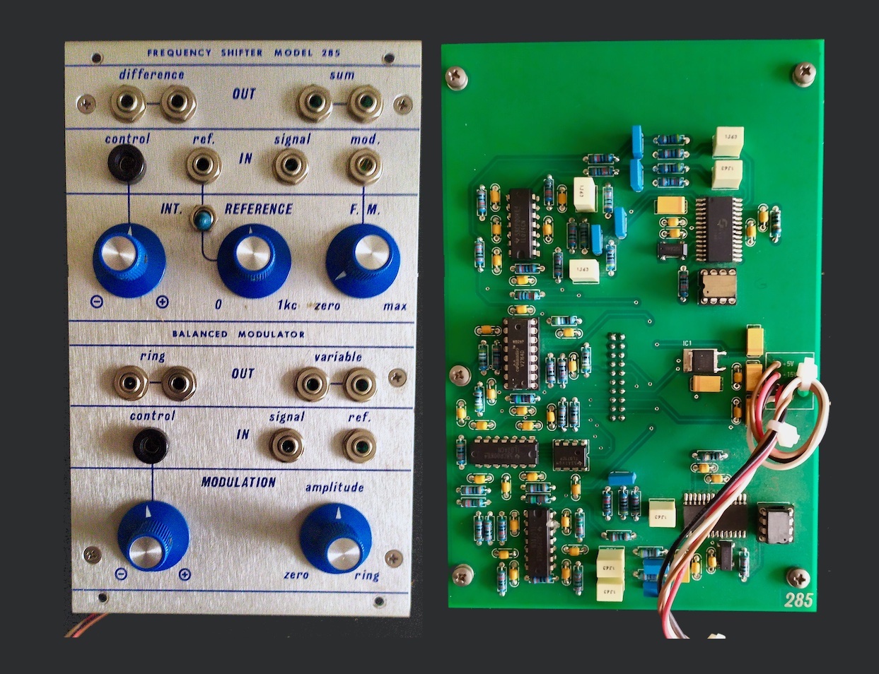
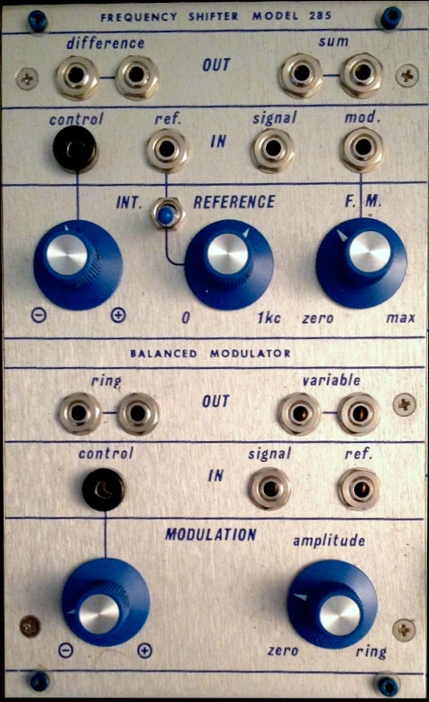 The Model 285 is Frequency Shifter and Ring Modulator. This combination is obvious because for Shifting the waveform is halved and only the positve values are heard. By increasing the offset-voltage the pitch raises (Shift). By connecting the negative wave component, the "counter-oscillation" comes into play and the Ring Modulation effect is generated. I call it effect, because it does not quite correspond to a "typical" Ring Modulation - it remains more to Ring-Mixer.
 I use the (newer?) fully analog and much more expensive and rarely found version of the Model 285, which - when installed - is outwardly identical to the first version. The boards of the fully analog module are much more densely populated and instead of to (MkI) there are three boards with a whole 27 trimmers (!!) - I haven't seen anything like that on a module before. I'm a bit scared about the service that will be required at some point! So far I'm very happy to own this module, especially because it reproduces the low frequencies more distinctly in ring modulation - and I'm a self-confessed RM nerd..
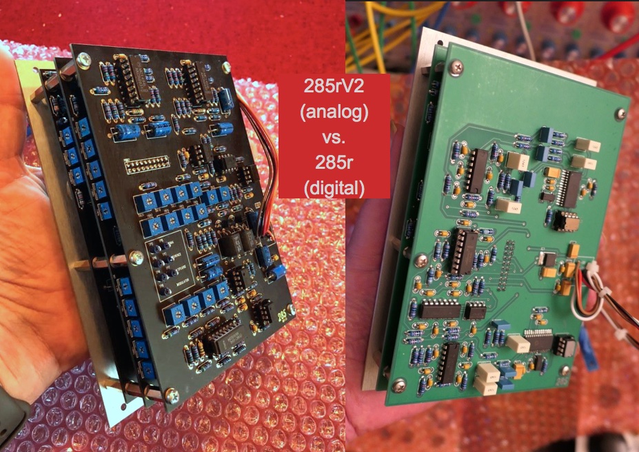 The more common and significantly more affordable version of the Model 285 is the first version, which is still popular. It works digitally and can be identified by the 4th power cable, which carries 5V for the "digital supply". The circuit is probably built around a chip of the TipTop Audio Z-DSP. I wasn't all that convinced by the sonic performance of this version and find that both shifting and ring modulation sound much better with my MAX-patch.
Perhaps the digital version has a right to exist because of the far lower price. The components of the analog version alone are already considerably more expensive than a ready-built module of the 1st version. It seems to be sufficient for most owners.
Quad Voltage Processor 254v
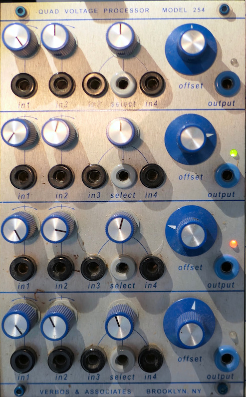 The "Quad Voltage Processor 254v" is very similar to the "Model 257" and has been developed by Mark Verbos. Incoming CV values can be bent and modulated here according to any standards. I got it to keep a little "modular feeling" within the instrument, because I mainly generate CV from my MAX patches using the computer. That gives me four computer-independent manglers with offset controls that keep the autonomy within the instrument.
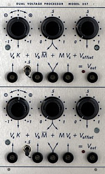 Basically, the 254v is two Buchla "Model 257" with an additional voltage input in each of the four rows. However, the processor of the "254v" is clocked much higher than that of the "Model 257", which means it offers clear advantages. Due to the additional input, the "254v" also carries a few genes of the "Model 256" (Voltage Adder). The only limitation was that the mathematical equations of the "Buchla 257" apparently no longer found enough space anywhere on the panel.
For me, the Model 254v is a very important module for being able to perform individual " manipulations" of the CV signals being sent by the computer with the instrument itself. The module completely softens (in my case) the boundary between computer and instrument. Also the offset is (on the instrument) worth its weight in gold.
Infinite Phase Shifter Model 297
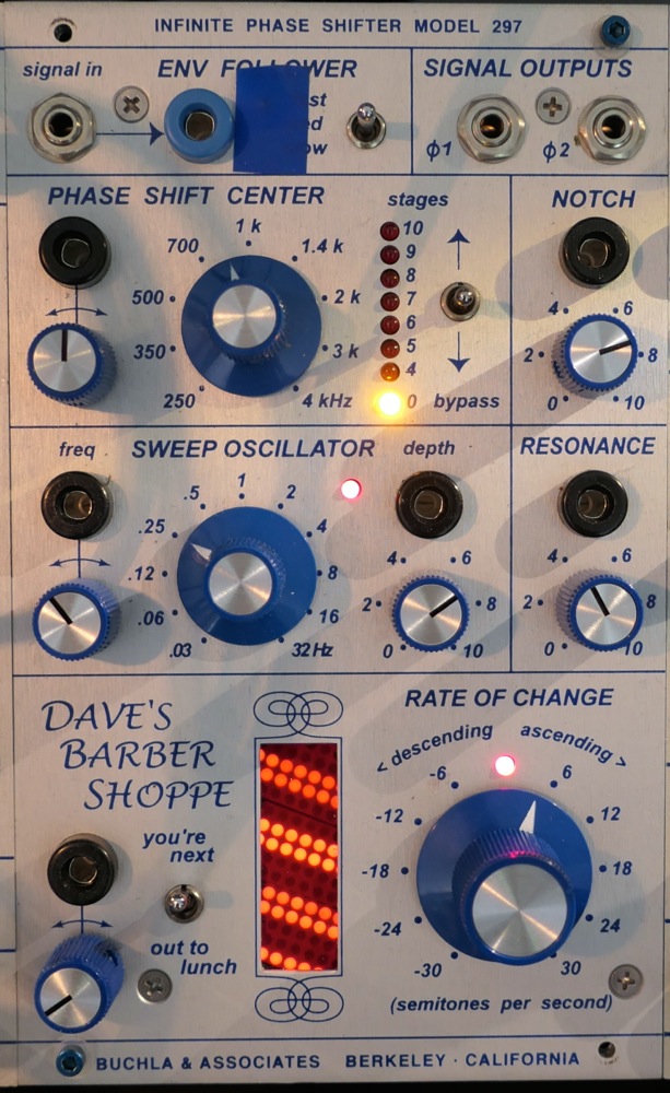 The "Model 297" is an original from Buchla and is still being manufactured to this day. Nevertheless, it does not belong in the e-Series, because it cannot store any values. That can be recognized at the originally white potentiometer caps (white = not storable). On my module, because of the uniform appearance, I have attached the blue Rogan poti caps. The blue tape covers the blue LED of the Env-Follower, which almost causes blindness, if it is not covered.
A really well equipped Phase Shifter: Next to the audio input is first of all an Envelope Follower in order to use amplitude related values. The size of the phase is set below, at the "Phase Shift Center". Next to it the number of stages is being set and on the right a notch (a cutout / filter) can be applied. The "Sweep Oscillator" is responsible for stronger internal movements and its effect intensity can be controlled via Depth. Next to it is the Resonance control (for the notch) - quite a boost to the power of the modulator. All parameters can also be modulated via CV inputs.
Especially the lower part of the module makes this phase shifter special: "Dave's Barber Shoppe" allows to create upward or downward only phases - called "barber pole effect". Up and down variations are likewise available. The big knob is used to control the rate of movement or as an offset knob for incoming CV signals.
Programmable Spectral Processor Model 296
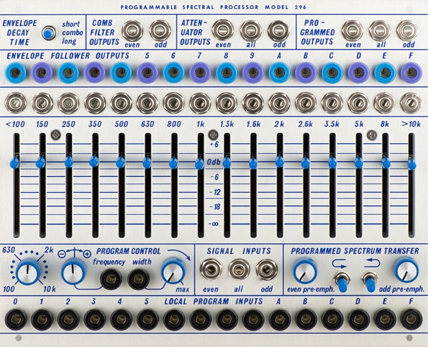 The Model 296 can be used as a Filterbank or, as the name "Programmable Spectral Processor" suggests, in a variety of ways for "audio processing". Actually, the 296 accommodates three modules. The sliders are exclusively connected with the function as a Filterbank. The corresponding outputs are in the middle. Soundwise the most interesting part is the "Programmed Spectrum" area - Audio Out top right. The sliders have no influence here, but the (black) CV inputs. For all 16 frequency bands, there are Envelope Follower CV Outs (blue/violet) and individual Audio Outputs. Almost as an addition I see the Comb Filter - Output in the upper left. The combination of the functions, I/O's and the distribution of the Audio Inputs in "Even" and "Odd" (2x8) also allow a Vocoder-like use of the 296 - that is precisely the Spectral Processing.
The Model 296 also illustrates particularly well why Buchla is well suited to work in conjunction with computers, tapes or instruments (the line audio levels used are very beneficial in this regard as well). With Buchla, the Inputs are usually at the bottom and the Outputs at the top of the modules.
Dual Matrix Mixer Model 205
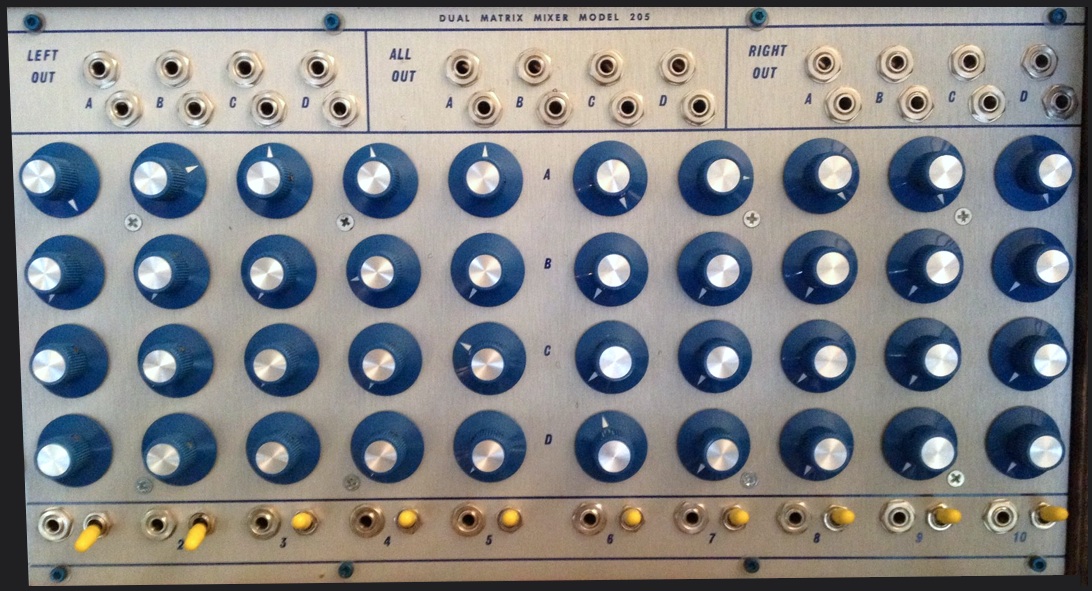 Even though the "Dual Matrix Mixer 205" completely contradicts my requirements - it's huge and can't be CV controlled - I couldn't resist it. Each of the 10 inputs can be controlled on 4 buses. The 4 busses are available in pairs as "left" (1-5), "right" (6-10) and "all" (1-10).
The switches are actually monitor switches for internal connection to the Model 227 (system interface). Input 1-5 are Monitor-Left and Input 6-10 are Monitor-Right. I use "Monitor-Right" as an aux output and have placed a jack output for it on the back of the instrument. That's where the pedalboard with Boost, Overdrive, Fuzz, Phaser, Delay and Reverb can be attached.
The Mixer 205 is to be considered as a sub-mixer. It allows, especially for the Model 296 "Spectral Processor", a much improved exploitation. The inputs are at the bottom, the outputs at the top, the knobs for outputs A, B, C and D are arranged vertically.
Source of Uncertainty Model 266
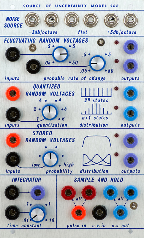 A particularly popular module, which is inextricably linked to the name Buchla, is the "Source of Uncertainty Model 266". This module is probably the model of most Random Generators produced today.
From Top to Bottom:
There are 3x2 noise outputs in the top row at -3dB, 0dB and +3dB levels. This is very "nice" and many Random Generators do not offer this. The randomness in these generators is of course generated by noise. In the second row 2x "Fluctuating Random Voltages" are produced - even without being triggered. The intensity of the movement is set via the CV inputs or controllers..
The central "Quantized Random Voltages" and "Stored Random Voltages" represent the actual random generator. The lower outputs provide the "main values", the upper outputs provide the probability distribution curve.
On the bottom row is the "integrator" (left) and flexes CV from *0.1 to *10. To the right a S/H unit makes the module complete! The pulse outputs are different: left ascending curve and right descending curve as triggers (On/Off).
The Pulse Inputs (Trigger) are orange, the Pulse Outputs are red. The CV inputs are black and the CV outputs are blue/purple. The metallic jacks are audio jacks, in pairs again - here they are (noise) outputs to be used.
Signal Delay Unit Model 277
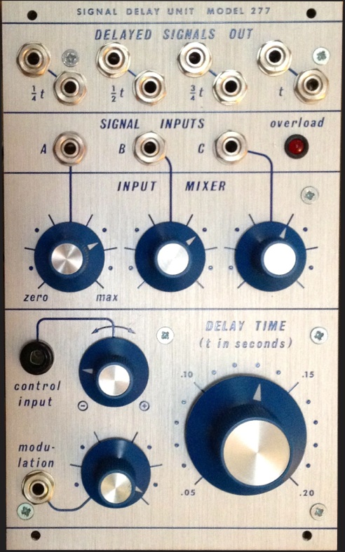 I had the "Signal Delay Unit Model 277" in my instrument only for a short time. This delay is another special module, because it has never been produced by Buchla. If I am informed correctly, it was developed by Roman Filipov (Sputnik)! The 1/4, 1/2 and 3/4 outputs are there to add feedback.
I was keen on having a Delay in the instrument in order to avoid a double ADDA conversion. But with the TC Electronic Flashback I already owned a delay and thus also a benchmark. I am not convinced of the sound of the 277 Delay - although it probably has many devotees. I think it has to do with the digital components or the programming, because both digital modules (285 and 277) in my instrument could not convince me for the same sonic reasons. In everyday life I rather prefer to use the delays of my pedalboard - also because it can be shaped a bit more with the boost of the Lehle D.Loop.
System Interface Model 227e
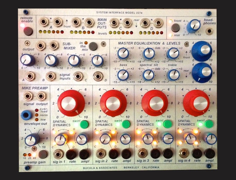 The sole module of the current "200e Series" in my instrument is the "System Interface 227e". However, mine is optically adapted to the historical "200 Series" (Rogan pot caps). I preferred the current 227e module to the historical 227 because its only half the size and much easier to get. It also tends to fit even better with current digital equipment. The 227e features a mic pre with envelope follower, a headphone amp, a 4 in 1 submixer and 4 inputs and outputs. Each output can be levelled separately and has its own "swirl" generator for 4-channel rotations (direction/rate/amplitude). Output 1+2 and 3+4 each have a 3 band equalizer and master volume. Four meters with 6 LEDs each show the output levels. Although the mixer outputs could be replaced quite easily with a MAX patch, the additional functions (mic-pre, submixer, headphones) might be badly missed. The EQ's prior to the outputs are also welcome.
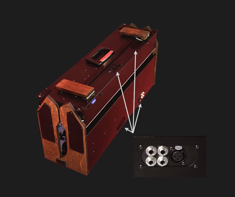
The "System Interface 227e" also includes a breakout panel on the rear of the case. The four Outputs are available as 6,3mm TS Jacks and it has a XLR Microphone Input.
Parts
Screws
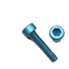 Getting inch screws is still a challenge in Germany. For fixing the modules I got blue Socket Head Cap Screws. They are a little longer than the Buchla screws (but actually shorter than in the photo), which is fine to me because the shorter Buchla screws tend to pop out if the threads are a bit worn out. The shipping was hassle-free and was very fast.
Pot-Caps
With the 200 Series, Buchla moved from the black Davies Knobs to the blue and red Rogan Knobs. Although the black Davies Knobs look better visually and also feel better in the twisting, I, triggered by the 205 Mixer, exchanged the Davis Knobs for Rogans on all modules, except for the VCOs because the position line of the Davies is recognized incredibly badly. That "consumes" too much attention while playing. In the dense colonization of the Model 205 (with 40 Pots) also more room for the fingers remains with the Rogans, because they are not as thick as the Davies.
Shopping
All these special parts are often quite difficult to obtain and the prices can be astronomical! Therefore it is essential to search thoroughly. There are some helpful forums, like Sequencer.de or Modwiggler.com.
Whether Rogan knobs, Tiny-Jax, Buchla Boats, busboards or patch cables.
Buchla Links
Tini Jax
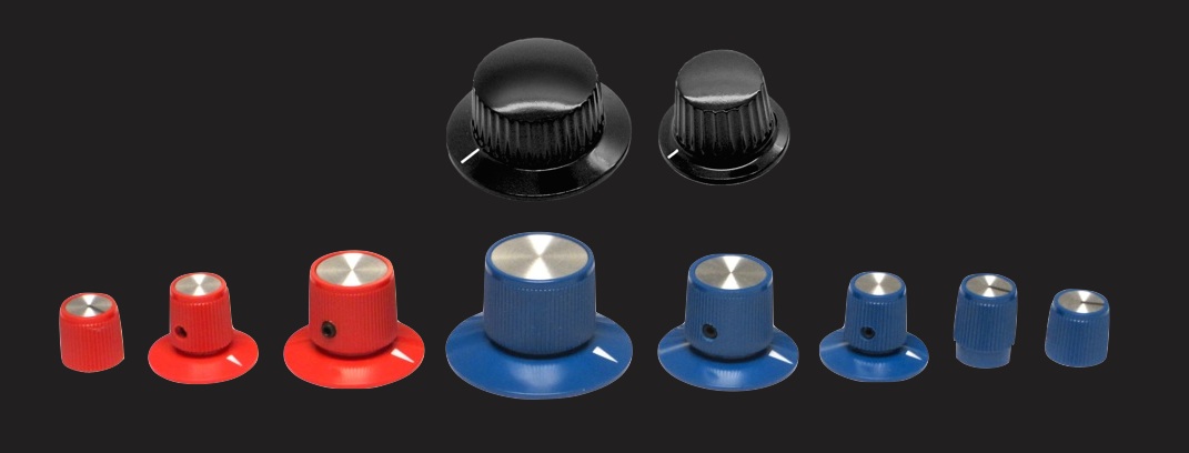
Buchla patch cables are hard to find and very expensive. That's why I initially only used mini jack patch cords. Finally I soldered myself patch cables.
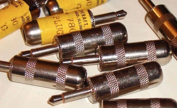
Because the cheaper plug models with plastic cap "740 .141" do not appeal to me that much, I decided to use the "780 .141" made of metal (shielded). Tini-Jax .141 plugs are only available from Switchcraft.
Since the cable aperture of the plugs is only about 5.5mm large, the cable selection is somewhat limited. My choice was "The" Goblin from Sommer Cable in the (moderate) colors red and ice gray. Great cable - and fits in perfectly together with a heat shrink tube.
Bananas
Buchla likes Pomona cables - and Pomona Electronics sells the nicest Banana-patchcables. In Germany they can be purchased via Mouser oder Digikey.
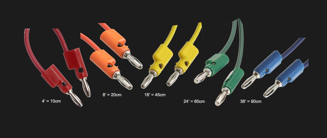
Buchla follows a color coding with the cables as well.
 Pomona - Digikey Website
Pomona - Mouser Website
There are also less expensive cables from other manufacturers. I recommend choosing plug length of 15mm in that case (there are also 17mm).
Tini Jax II
 By chance I came across a used set of the old Mini-Tiny Patch Cables, that were only available for a short time at Buchla. Actually I had disregarded them because of the plastic caps, but as I have the Model 296, which can hold a maximum of 61 (!!) Patchcords, I thought it might create a bit more overview and easier access to the module.
The idea was spot on. Plugs and wires are of good quality and the overview has improved tremendously! A comparison image will open by clicking on the image.
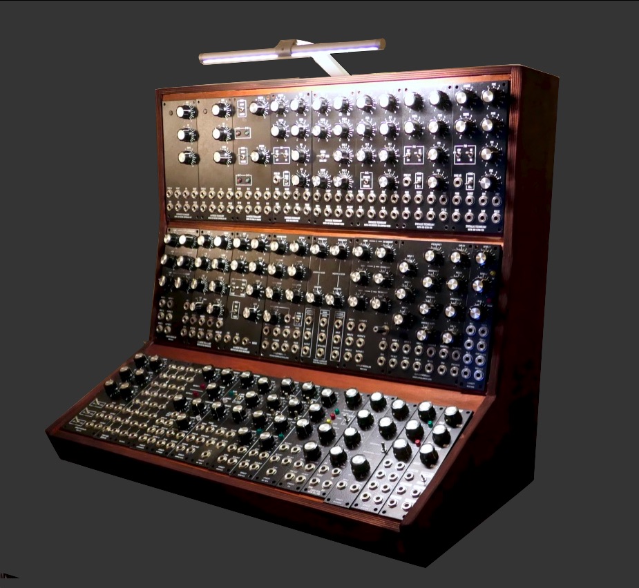
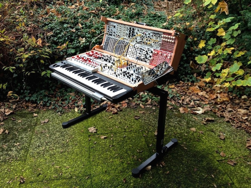
Foldable
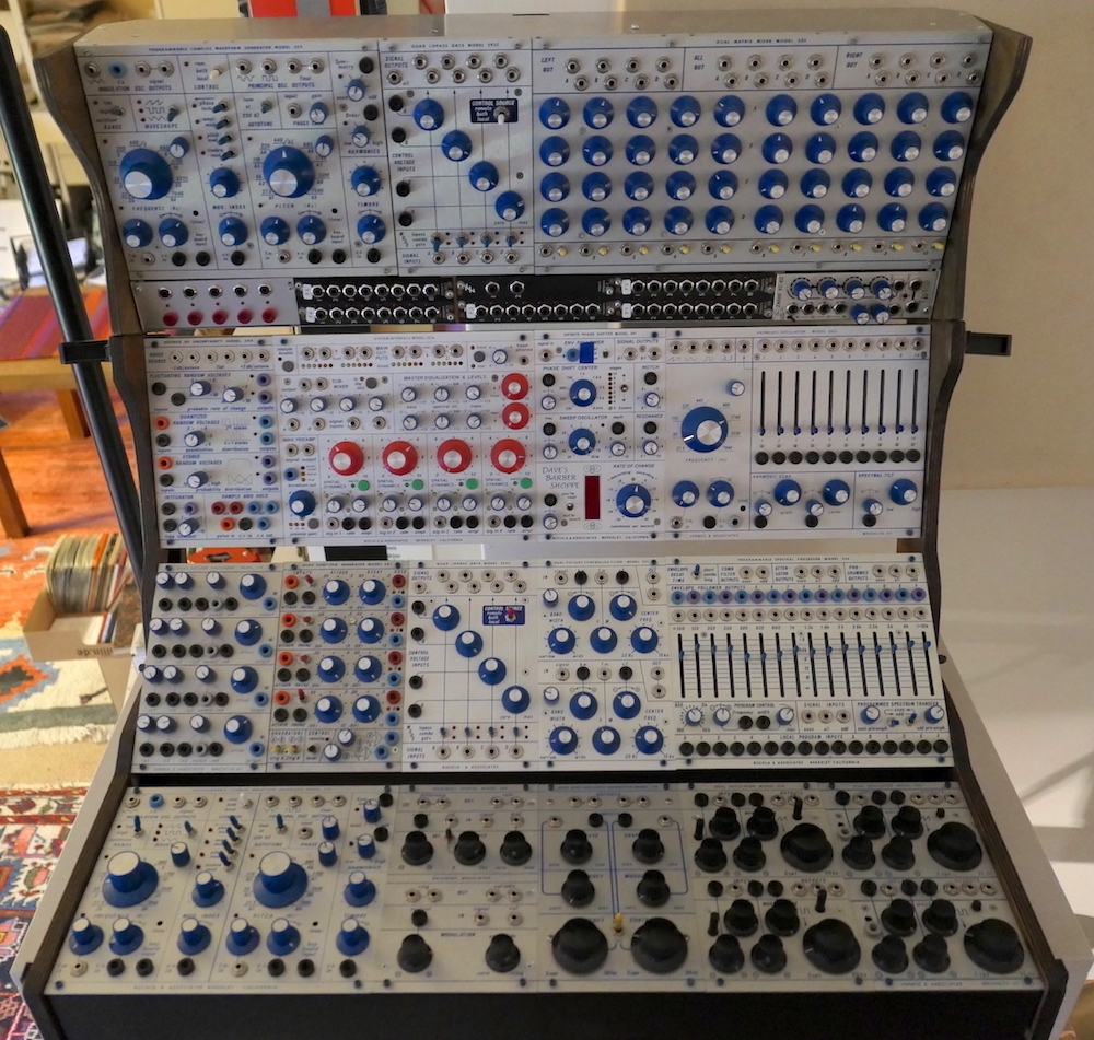
My modules are housed in a "201e-18 Powered Cabinet" - the same as seen in the 200e series photo (above). It consists of three rows of module racks called "Boats". The "U" (Unit-) divisions denote the width of the modules. So 3x6=18x 1U modules will fit into the case. As seen, there are also double and triple module sizes. With a folded or closed case, the three 6U boats are nested very tightly and the center boat is then located behind the sides of the outer boats. This makes it inevitable to remove all patch cables for transportation.
This folding-case concept is so consistently oriented to reduction with a low weight, that it has won the consideration against a patched transport.
Because of the segregation of CV and Audio (Banana, Tini Jax) and a lower module number the effort of patching is not comparable with MOTM or Eurorack. It's noticeably faster. So you do not forget where cables are patched.
Buchla Cases have small holes in the boats, which are intended for rear panel connectors. The Breakout Panels are installed from the inside, such as the Back-Panel of the 227e System Interface (seen in the picture). XLR Mic In and 4x Jack (6.3mm) Out. Good thinking!
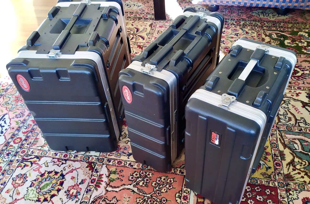
The 201e-Case is incredibly light weighted! That too was a criterion for me, but it's not difficult to recognize that the instrument is not well protected. There are special Hardcases, though a lot of air make them much larger than the folded instrument.
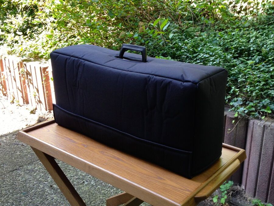
For transport, I ordered a cover from Hot-Covers: a custom-made "pullover" that protects the instrument while being super light and very convenient. The cover has a bottom with Velcro closure as well, which is simply swiped shut. At £48.-, this cover was also significantly less expensive than a hard case! Just sending the dimensions (of the case) by mail is all you need to do.
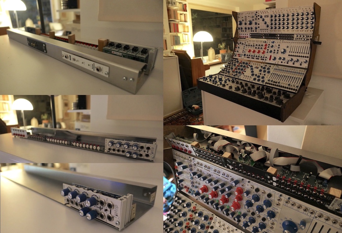
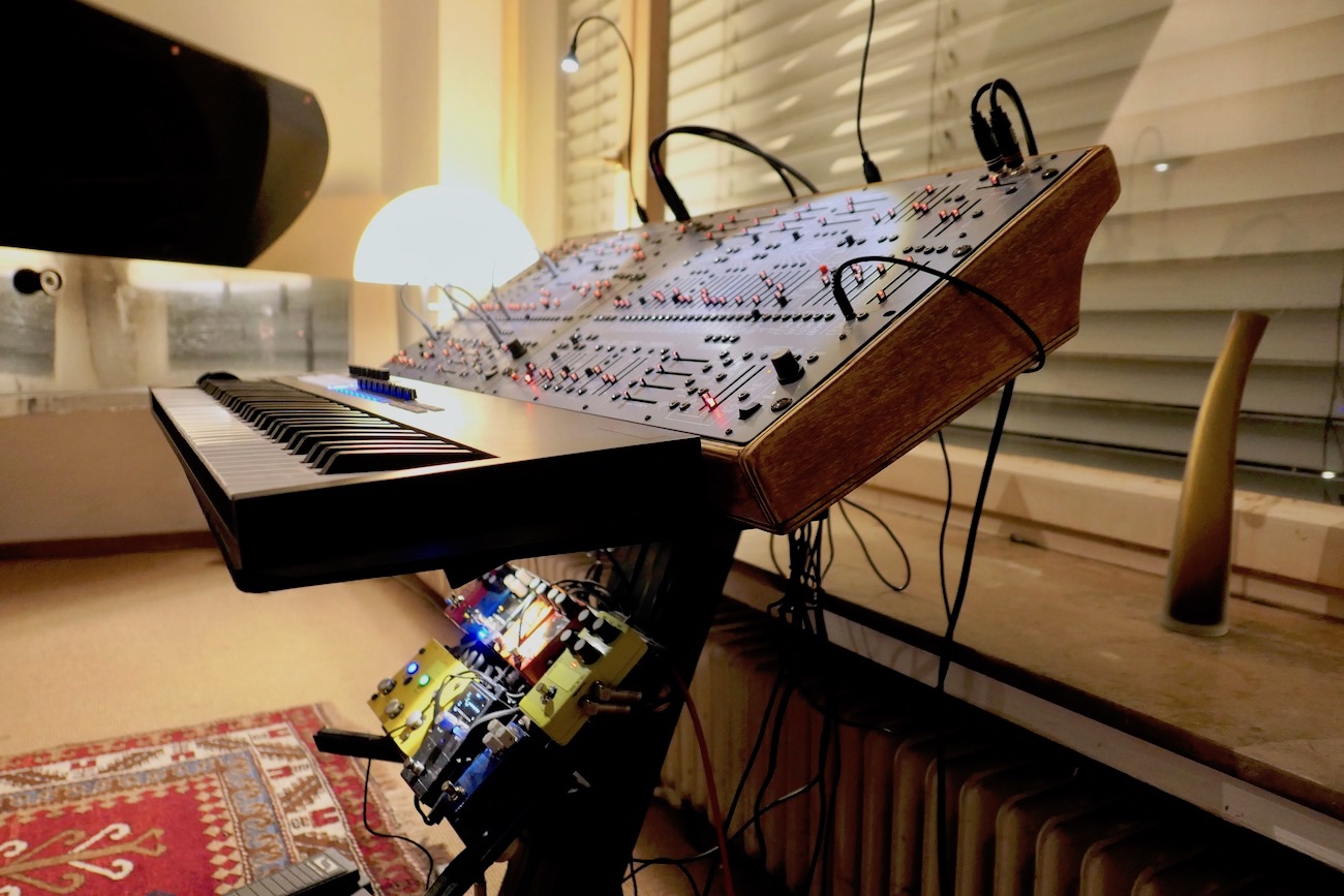
Expansion Boat
The extra 6U boat on my Buchla 201e-18, is from a third-party manufacturer. Underneath (where the wooden bars are) I added a 4cm height steel U-plate for the Eurorack modules from Expert Sleepers, which receive CV from the computer or send it from the Buchla to the computer. The wooden side panels I have fabricated myself. The top part is attached to the Buchla case by two case Drawbolts. The power is transferred via a 4-pin XLR connection from the lower case.
 I placed the grounding of the Eurorack modules on the outside of the case, in order to easily separate the systems (Buchla + Eurorack) for testing in case of a humming problem. The ground wire runs to the 201e case's ground output.
Because the case quickly became too small for all the modules, I first had built a removable top-boat for the Eurorack modules, then purchased another Buchla-Boat and put the Euro-Boat on it. But that was too tall for me (... stories from the life of a modular synth owner).
After several more attempts, I finally got a U-profile built to accommodate the Expert Sleepers modules laying horizontally and across the entire width (65cm). I attached the U-profile together with the Buchla-Boat to the self-made Cheeks (side parts), to make it a single part that can be taken off for transport. The expansion boat is attached to the Buchla Casing with two case fasteners.
 The company that made the U-profile for me (€23.- incl. shipping) has surprised me so positively - not just because of the low price - that I am very pleased to recommend them. The few holes and two cutouts for power and SPDIF I/O modules I have done by myself.
U-Profil Article Number: C010102-U:
U-Profile from sheet metal, steel, thickness 1,0 mm
Thigh dimension A: 30 mm
Thigh dimension B: 40 mm
Thigh dimension C: 110 mm
Angle α + β: 90º
Length: 650 mm (Buchla-Cabinet Width)
The Eurorack inside my Buchla
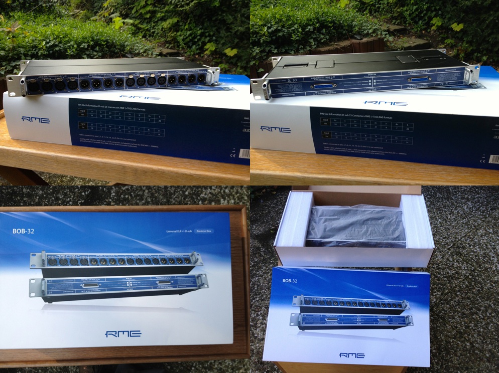
In order to control the Buchla from MAX, I am using Expert-Sleepers Audio-to-CV modules, which are only available in Eurorack format. Having built the Expansion-Boat myself, I took the chance to integrate the Eurorack discreetly (and crosswise). The power module and the ES-40 (SPDIF I/O), 10TE, are located on the rear of the instrument.
On the picture the top row shows the modules that are in the Buchla (including the ones on the rear side):

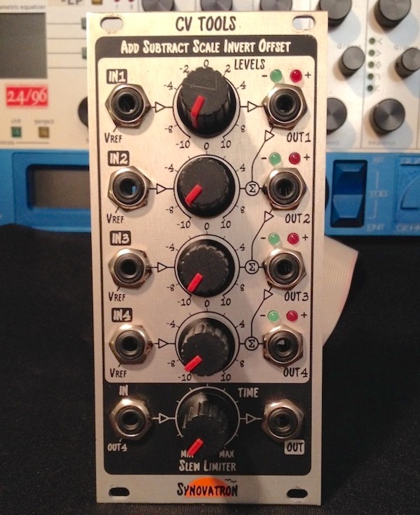
There is a Gate-to-Pulse Converter from Synovatron connected to the Gate Expander (8x Trigger/Gate) of the Expert Sleepers Block (red) to generate the specific Buchla Pulses (4ms 10V Peak with 5V Gate). Since my instrument has hardly any Pulse inputs, I get along with the 5 Pulses. More about Expert-Sleepers and the Pulse-Converter see below (Buchla features).
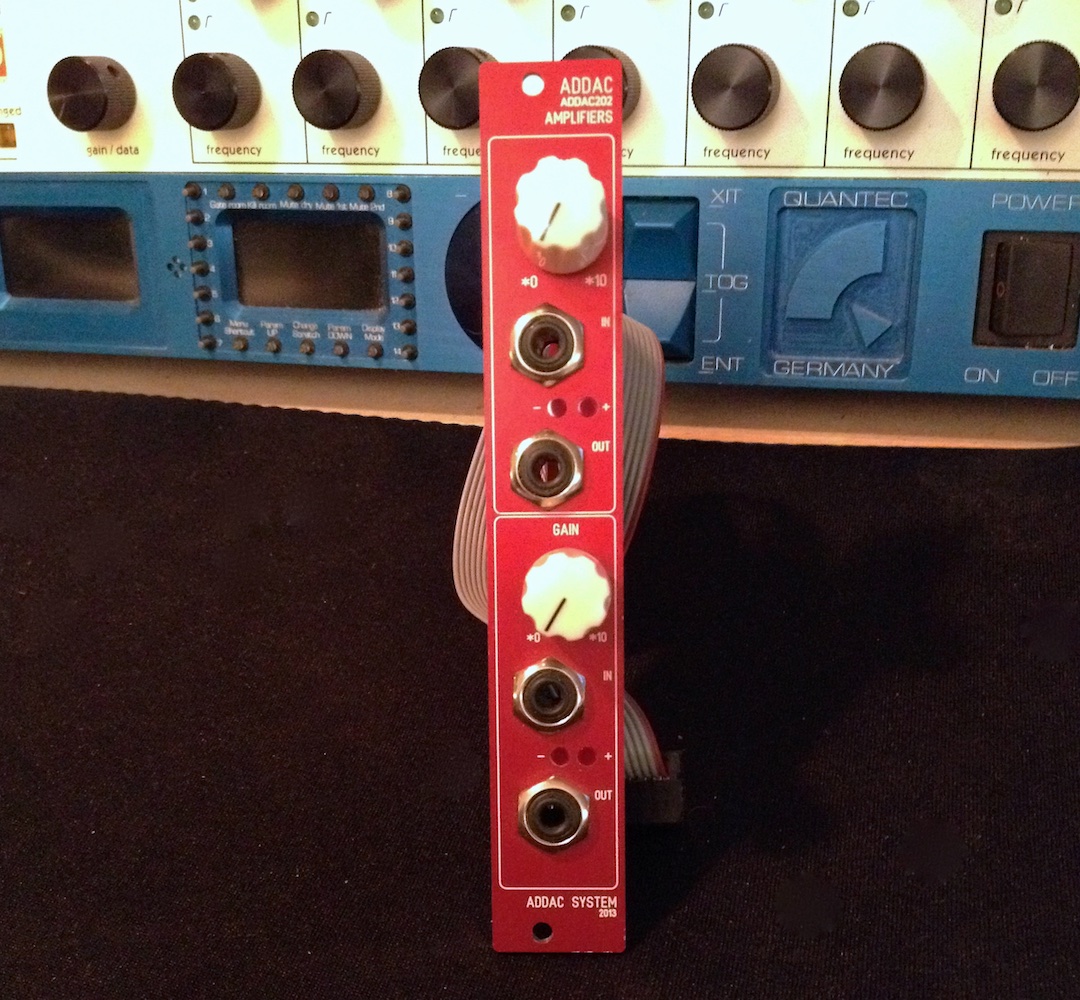
I use the remaining 8HP on the front for a Foot-Control module from ADDAC. It allows to connect an Expression- and a Sustain-Pedal. Next to it is a µVeils Dual VCA for the "Mix" outputs of the two Vektor Mixers (in the other case). I control one of the two VCAs with the Expression (Volume-) Pedal.
The two Planar Vektor Mixer modules (with Joystick) I keep in a mini case in front of the Buchla. The 2x 4 audio inputs are sent via a Doepfer "Multicore" set to the Planar modules. All 8 channels are sent via Ethernet cable. The alternative would be quite a cable chaos with 8 long cables crisscrossing the instrument. The two mono mix outs of the Planar modules return via another Ethernet cable - into a dual VCA, which I use to control the volume of the mix outputs.
Buchla peculiarities of CV control by other formats
UNIPOLAR VS. BIPOLAR: The big difference to other modular formats is the uni-polarity. This means that Buchla only wants positive values (0-10V), while bi-polar systems process ±5V. So both are 10V pp and theoretically a 5V offset shift should be sufficient. But in practice it is rather different.
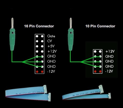 If a different system is connected, it is first required to connect the grounding of both systems. On Buchla instruments there is a banana jack (on the back) for this purpose. On the left, you can see how to set up a suitable cable in another system, with the example "Eurorack" (16 and 10 pin ribbon cables are the typical connections in the Eurorack). This already is the main point for a successful integration.
Grounding problems will show up as humming noises. In order to perform a quick analysis in case of such disturbances, I therefore recommend to make this connection not internally, but externally - through a banana cable. With the external connection, the systems can be electrically isolated from each other in an straightforward manner for individual testing.
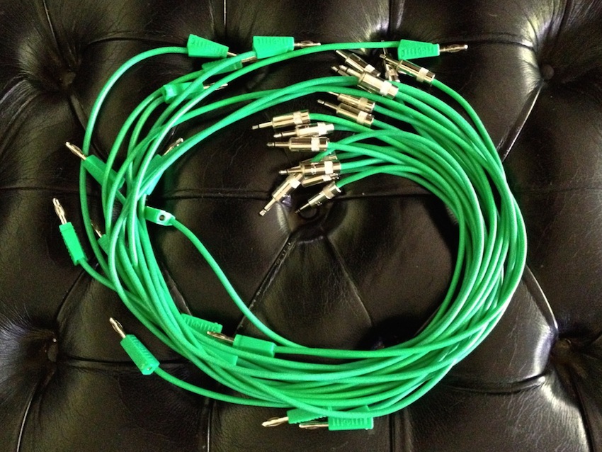 To connect from the Expert Sleepers modules, I manufactured my own adapter cords. Since only the TIP connection needs to be plugged in, this was very easy and very cheap. I took very inexpensive "extra long" banana plug test leads, sliced the cables and attached mini jack plugs on the cable side. One banana cable thus turned into two adapter cables (at half the work. Simultaneously I introduced the Color Code "Green" for CV cables from the computer ( on my system).
0-10V - Unipolar
With CV control now, with the Eurorack Expert-Sleepers expanders, the ±5V comes into play: Buchla asks for 0-10V and the ESX-8CV module delivers ±5V as shipped. First thing that came to my mind was the jumper reposition - it changes the current to ±9.13V. Using just the positive values, it would be 0-9.13V. This could be used for most applications, but two problems remained: "the last volt", or 0.87V would be missing, and by omitting the negative values, only 11 bits (0-2047) would be left for control - although the resolution would still be quite high enough. However, I would rather use 12 bit - and that turned out to be much easier than originally thought.
 The image shows there are actually only 16 inputs in my instrument that really require 0-10V (because they do not have a dedicated Polarizer). My compromise, since I've never used all 16 inputs at the same time, is that I switched one (of the five) expanders (with 8x CV) to 9.13V/11bit control. Since (in this case) 10V represents +6dB, it's forgivable that I can't generate the 10V. Should I need these CV channels on other modules, I just have to set the Offset in a different way (and I only get an 11bit resolution). As an alternative or addition I can also use the Model 254v Quad Voltage Processor and alter the ±5V to 0-10V by setting the Offset to 12 o'clock. A very comfortable situation.
Since most CV inputs on the Buchla are connected to a potentiometer (= Polarizer), the pot can be used to control the Offset in the same way. In most cases this is even better than 0-10V, because e.g. at the "LoPass Gate 292" the pots would have to be in 0-position to be CV controlled. With ±5V the 0-position is shifted to 12 o'clock and this has the positive effect that the envelopes can be decreased when the potentiometer is set to values below 12 o'clock. In any case, this is very convenient for me.
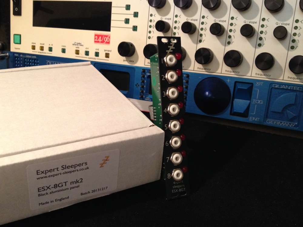
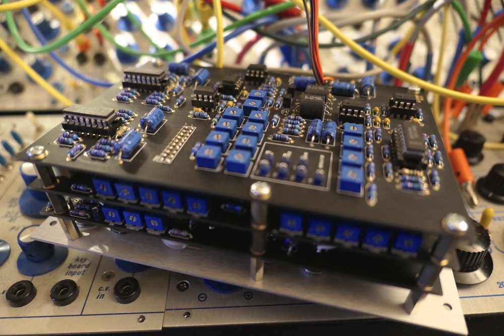
A view with the settings of my Expert Sleepers Expanders. It is one ESX-8GT MkI Gate Expander and four ESX-8CV CV Expanders.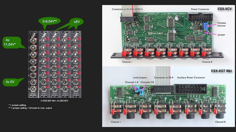
CV
Only one ESX-8CV expander is not in the delivery state: the jumper is set to ±9.13V and with the trimmer the output was maximized to 9.54V.
GATES
On the ESX-8GT MkI one of the level jumpers is set, so 4 outputs have 11.54V output (instead of 5V) - but this is only possible with the MkI modules as they are powered (ESX-8GT MkII modules are passive).
Buchla Pulses
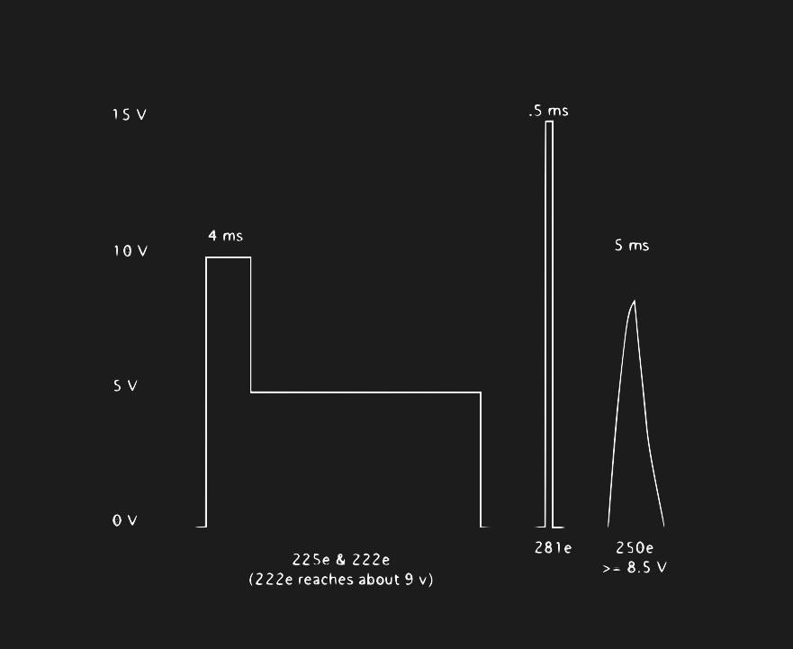
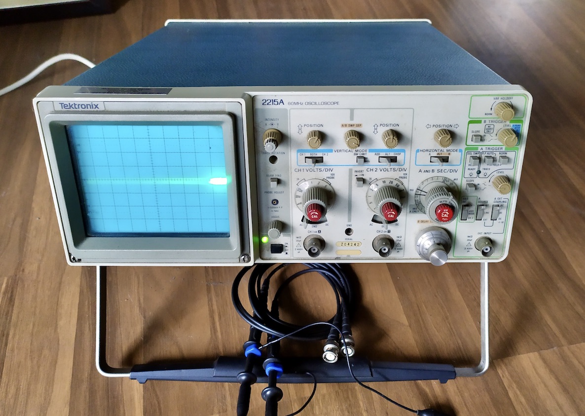
Buchla has very different pulses in different modules. In the graphics of Chris Muir this becomes evident. The key problem is that the Gates/Trigger/Pulses are not supposed to be longer than 4ms. The pulse of the "Function Generator 281" is even only 0.5 ms short. The second issue is that the typical Buchla " Stepped Pulse" consists of a >8.5V Trigger and a 5V Gate.
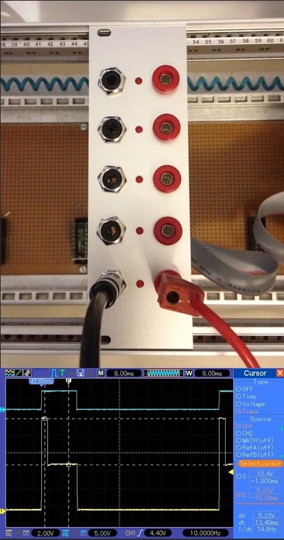
To keep it in a nutshell - the best solution is the GT Elements from Synovatron. On the photo, the incoming Gate can be seen in the monitor at the top and the Buchla Pulse generated from it can be seen below. Simply perfect!
1.2V/Octave
Synovatron provides a solution for this too, but I don't need it, because I create CV with MAX (cycling74). Only the 4ms at the trigger length of the pulses could turn out to be problematic and the swallowing of single signals at higher tempos would possibly occur and can be prevented only by the "Audio-Interrupt Mode" (MacOs). Of course I don't want that, because the name says it all (audio interrupt). For this I got the GT-Elements module.
Synthesizer
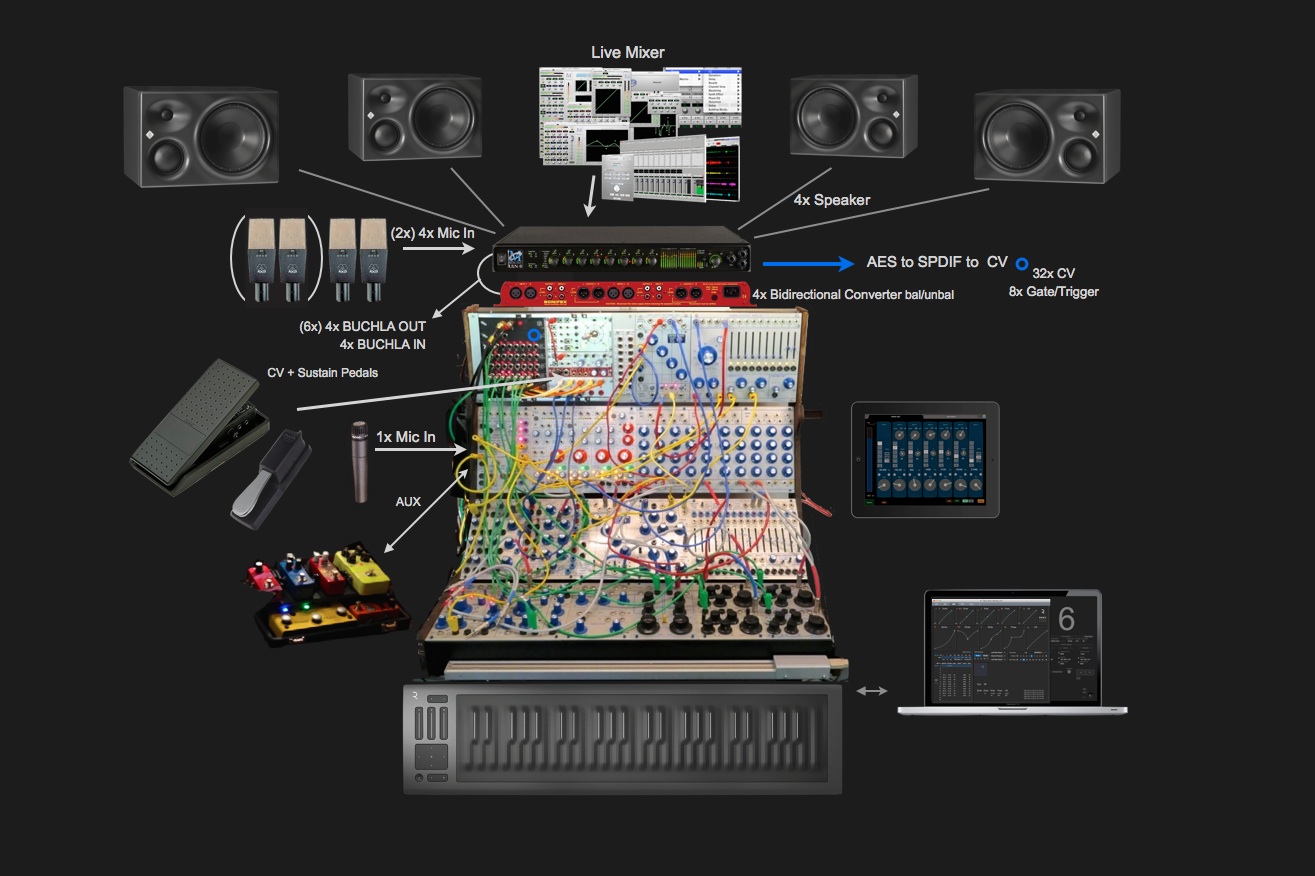 "Hybrid" in this case stands for analog modules and digital control. Control data is generated with the help of the computer and delivered to the synthesizer as CV (Control Voltage). My setup provides up to 80 CV outputs. Actually, it is the "dream instrument" that I had in mind for 30 years.
 The high-quality key data of this 5U format are defined, the circuits of the modules originated from all directions. Heavy construction. Above all, it is worth mentioning the high quality of the components, which, in addition to excellent audio quality, also leads to a very good tactile feel.
 The Behringer reinterpretation of the ARP 2600 has succeeded magnificently! The B-2600 sounds a bit tidier, less exuberant than the historic ARP 2600 originals. From my point of view it's THE new "People's Synthesizer".
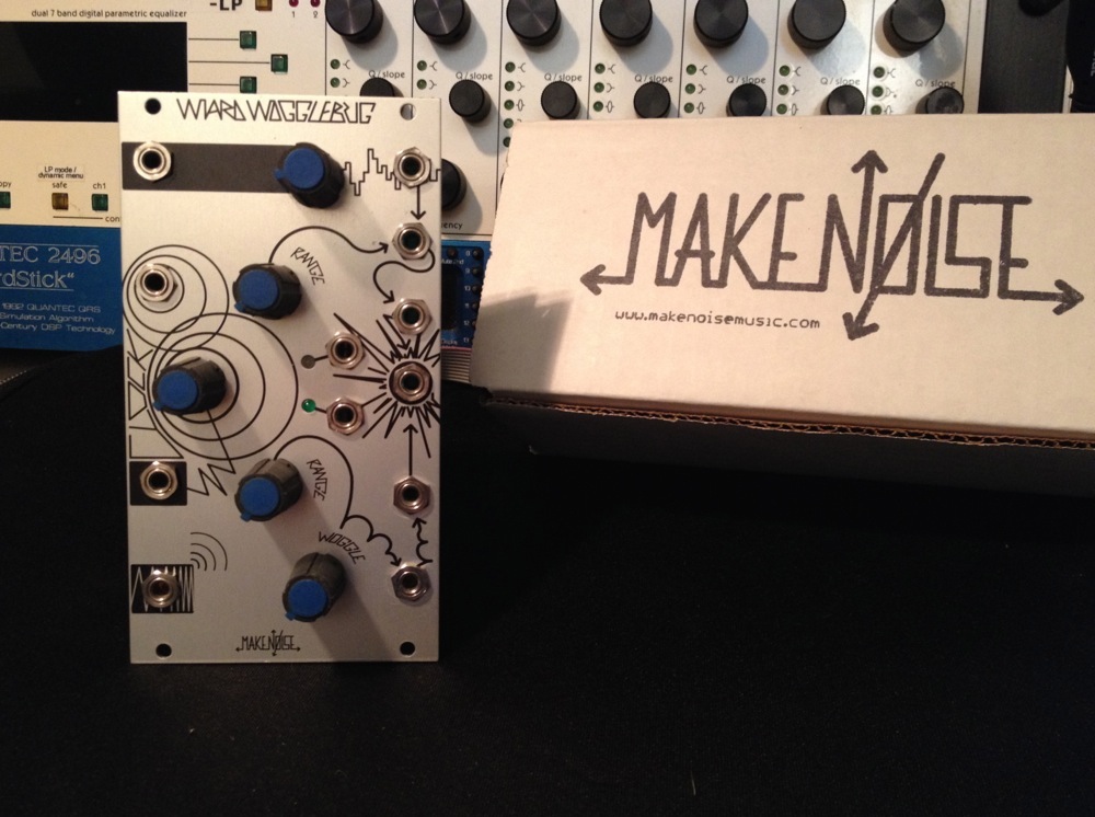
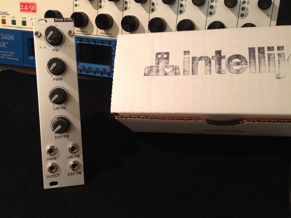
 The most widespread format(3U). My last Eurorack instrument - 600TE, easy to fold in patched state, however I didn't feel comfortable with the small Eurorack format. Nevertheless, I still enjoy some blessed Eurorack modules to this day.
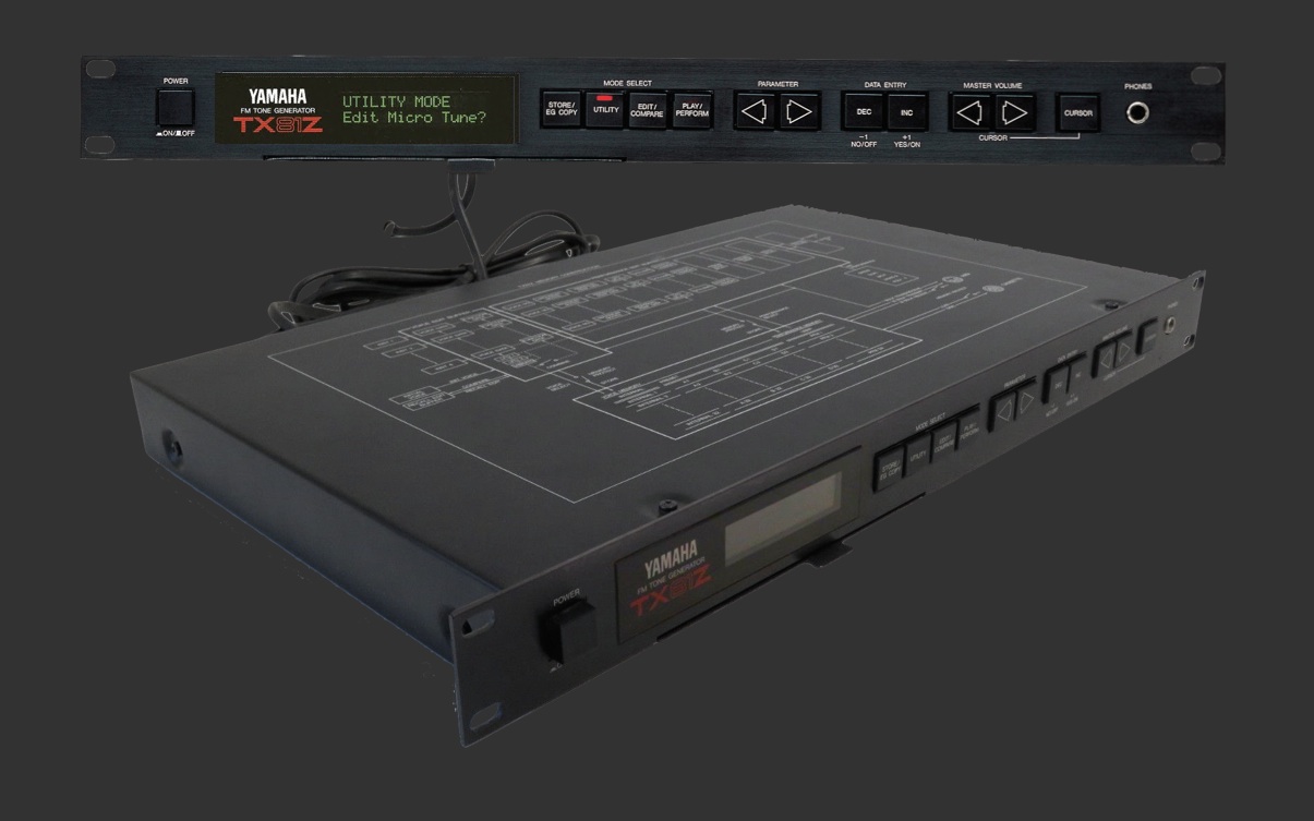 The TX81Z has 8 voices with 4 operators (= oscillators) each and was the first FM generator which provided the capability to also realize FM with non-sinusoidal waves. Because of its different tone generator it does sound better than the DX series.
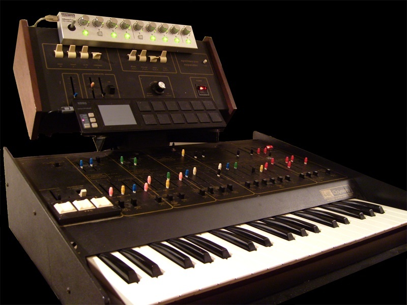 ARP instruments have been my choice since 1983. During the 80's and 90's Rhodes Chroma and ARP 2600, and since 2006, with the start of the " Hybrid Synth" project, it was this Odyssey featuring the Little Brother. An ARP overview from my perspective.
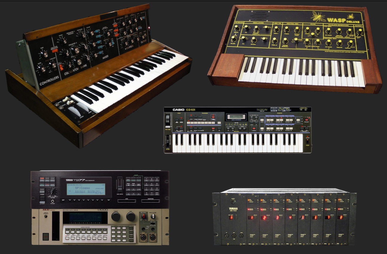 Some Classics that I had acquired in the modern era and the digital sound generators that I owned since the late 80's and with which I did a lot for about 5 years. They were especially interesting for me because of the computer and SysEx controllability.
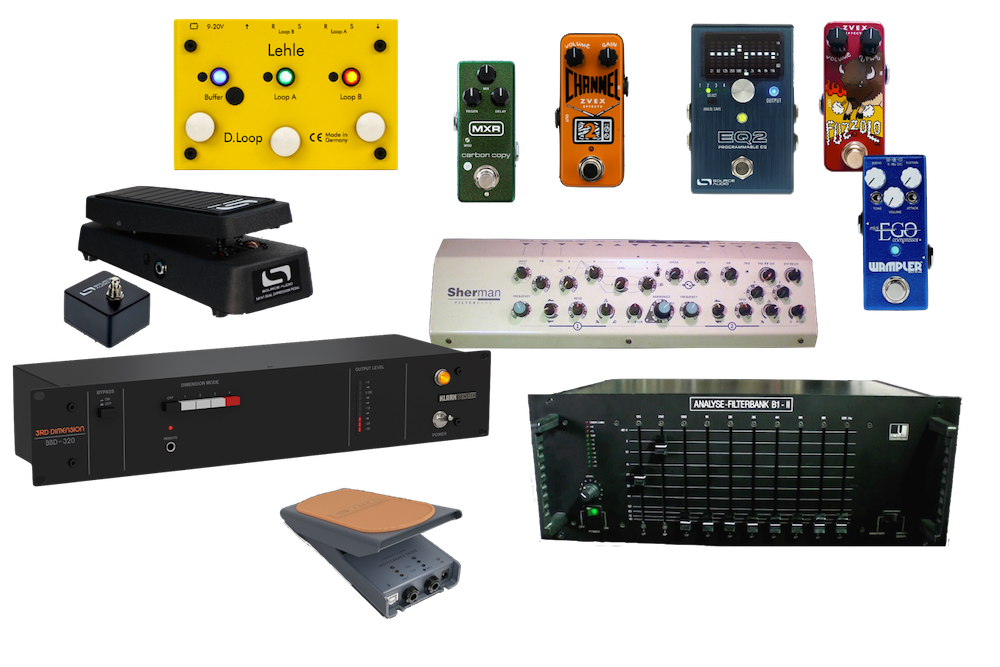 Synthesizers need FX devices!
Here is something about the peripherals: Filter Banks, EQ, Delays, Distortion, Phaser, Volume and Expression Pedals, Miniature MIDI Interface, Pedalboard and Power Supply.